Q2 Arithmetic Logic Unit
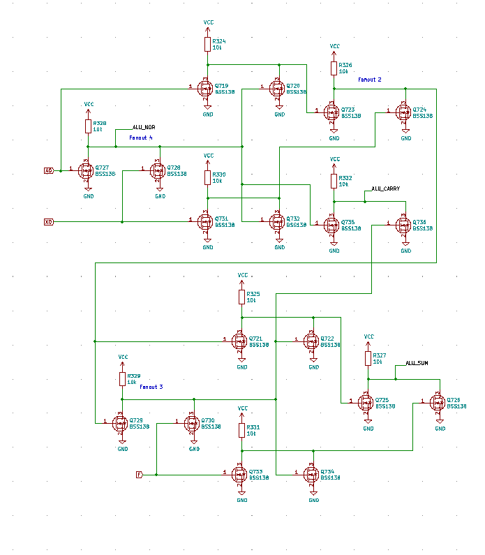
The ALU is bit-serial to reduce transistor count. During the 12 ALU states, the bits from A and X are shifted through the ALU least-significant first, and back to A. Depending on the opcode, the flag register tracks the carry or zero status.
To compute the sum, a standard binary full-adder made out of NOR gates is used. By using the NOR gate implementation, we can re-use the first gate for the NOR operation.
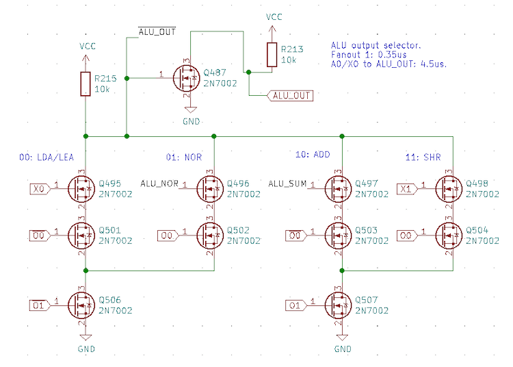
The ALU output selection is based on two bits from the opcode (note that LEA and LDA both have the same ALU function). The ALU uses these two bits to determine which output to use.
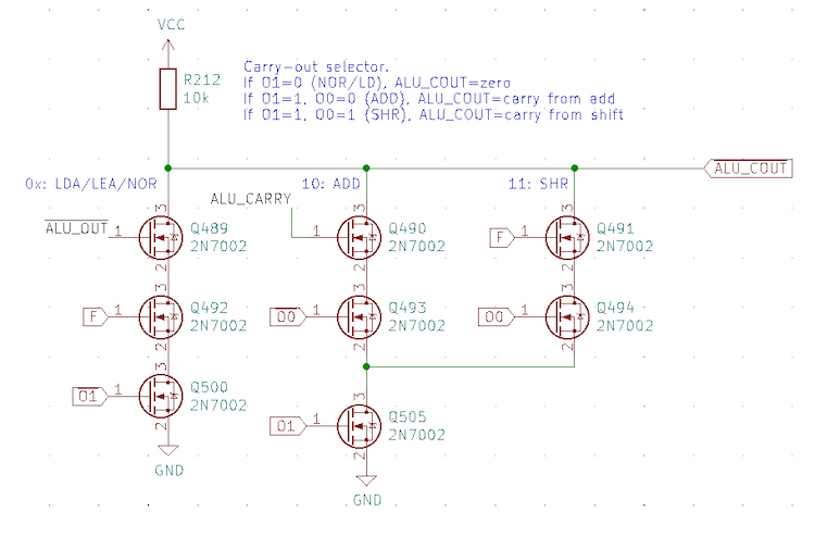
Finally, the ALU flag output also uses two bits from the opcode. Here the load and NOR operations clear the flag when a non-zero value is detected. The carry from the adder is used for ADDs, and the flag is preserved for shift right, (the flag will be set to X0 prior to the ALU state for shift right).
< Control Signals | Registers >