Q2 Control Signals
The control signals, which are used to cause the various pieces of the Q2 to do work, are driven from the operand register and decoded state. The simple instruction encoding and RISC-like instructions make the logic required to drive the control signals fairly small. This is in contrast to some architectures which go so far as to use a ROM.
Some of the control signals are driven directly from the state machine:
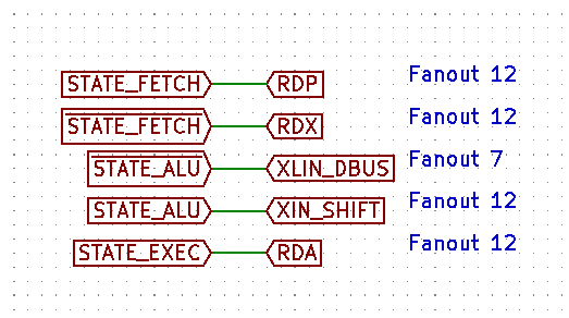
RDP causes the contents of the P register (the program counter) to be placed on the address bus. It is asserted during the FETCH state so that we can load the instruction to execute. Note that the Q2 will be in the FETCH state at reset, so this also allows us to use the P register for reading and writing memory from the front panel.
RDX causes the contents of the X register (the operand register) to be placed on the address bus. It is asserted during all states except the FETCH state. In the FETCH state we want P to be on the bus, but in all other states we either don't care or want X.
XLD causes the input of the low bits of the X register to the data bus. This is asserted in all states except the ALU state. In the ALU state, we want to shift X instead. However, in all other states, the low bits of X are loaded from the data bus (if they are loaded at all).
XIS causes the input of the X register (high and low bits) to be set to the shifted value (the input of X0 is set to X1, etc). This is asserted during the ALU state to shift the contents of the X register through the ALU.
RDA causes the contents of the A register (the accumulator) to be placed on the data bus. This is asserted during the EXEC state for the store instruction. Note that other instruction types do not care about the data bus during the EXEC state.
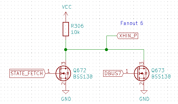
XHP sets the input of the high bits of the X register to the high bits of the P register. This is asserted if in the FETCH state and the zero-page bit is clear (DBUS7 is 0).
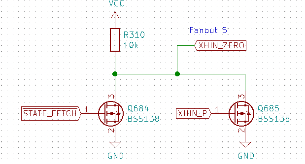
XHZ sets the input of the high bits of the X register to zero. This is asserted if in the FETCH state and XHP is 0. Together, XHP and XHZ determine how the high bits of the X register are set in the FETCH state: either to 0 if the zero-page bit is set or to the high bits of the program counter if the zero-page bit is not set.
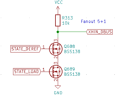
XHD sets the input of the high bits of the X register to the data bus. It is asserted in the DEREF and LOAD states, since during a dereference or load the X register gets set to the data bus.
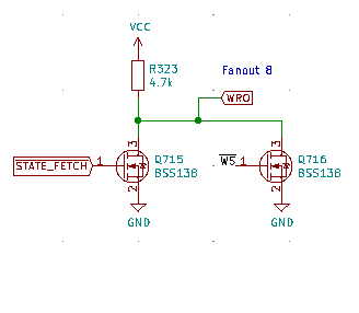
WRO causes the top 4 bits of the data bus to be loaded into the operand register. It is asserted in the FETCH state when the WS (write strobe) signal is high. This causes the Q2 to save the operand in the FETCH state after there has been enough time for the instruction to be stable on the data bus.
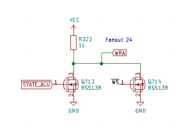
WRA causes the accumluator to be written. It is asserted in the ALU state when the WS signal is high. The accumulator always takes its input from its shifted value where the top-most bit is loaded from the output of the ALU. The ALU state will be active while WS is strobed 12 times.
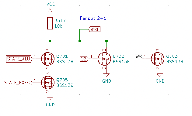
WRF causes the flag register to be written. It is asserted in either the ALU or EXEC states for instructions that update the flag (0xx instructions). During the EXEC state, the flag is loaded with an initial value and then it is updated as the accumulator and X register are shifted through the ALU.
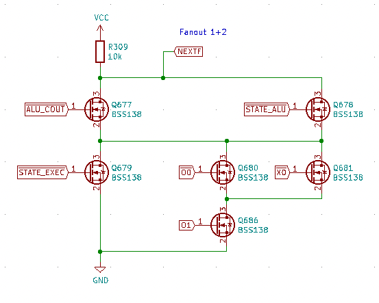
NEXTF is the input to the flag register. It determines what the next value of the flag will be set to when WRF is asserted. In the EXEC state, NEXTF will be asserted for LDA and NOR instructions since O1 will be zero for those instructions (000 and 001). For SHR (011) instructions in the EXEC state, NEXTF is set to X0 (the carry of the shift). Finally, for ADD (010) instructions in the EXEC state, NEXTF will be 0. In the ALU state, NEXTF is simply set to the carry output of the ALU.
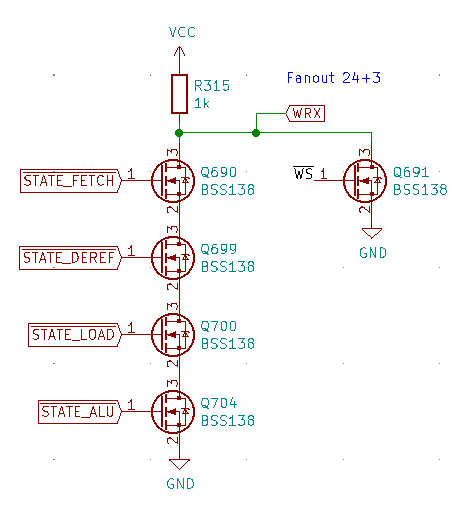
WRX causes the X register to be written. It is asserted in the FETCH, DEREF, LOAD, and ALU states when WS is high. Note that the X register is written in every state except the EXEC state. This would imply that we could simplify the logic somewhat, however, to simplify the state machine, when the LOAD or DEREF states are not used and empty state occurs, so we need to make sure to not write X in that case.
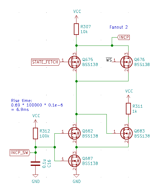
INCP increments the P register. The P register is incremented in the FETCH state when WS is high to move to the next instruction. It is also incremented when the NEXT switch is pressed. A Schmitt trigger with an RC delay is used to avoid switch bounce.
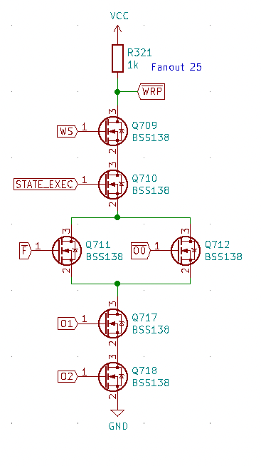
WRP causes the P register to be written when it is pulled to ground (active low). It is asserted (pulled low) when executing a JMP instruction (110) or when executing a JFC (111) instruction if the flag is clear.
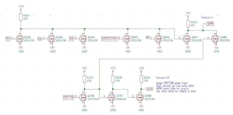
WRM causes a write to RAM when pulled to ground (active low). It is asserted in the EXEC state for STA instructions (101) or when the deposit switch is pressed.
DEP causes the front panel switches to be loaded on to the data bus. This is used to load the value of the switches into RAM.