Q1 Modules
The Q1 is comprised of modules, each on a 13x25 cm board with 40-pin connectors. Here's a detailed look at each module.
ALU Modules
| Module | Description | Parts | Images |
|---|---|---|---|
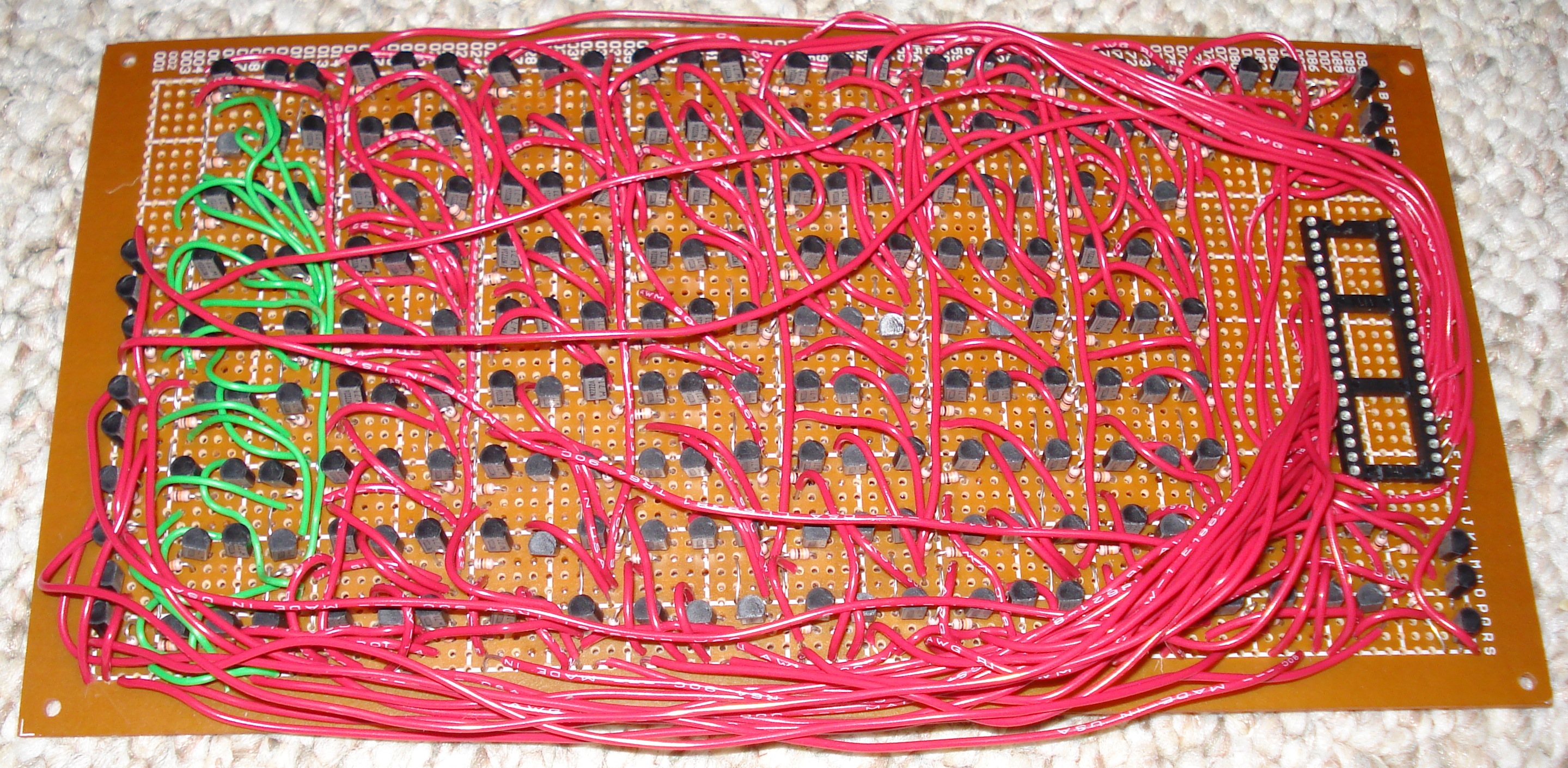
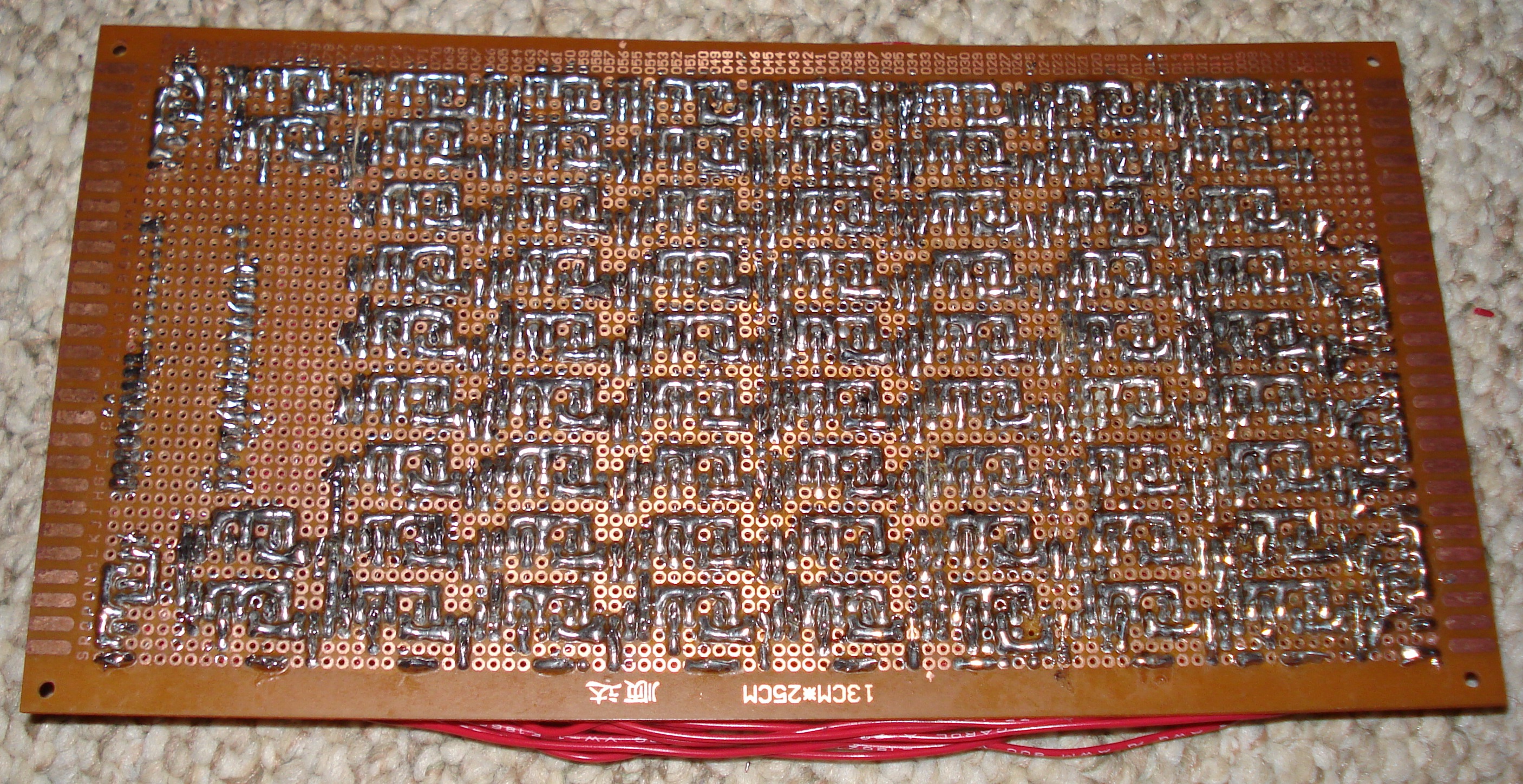
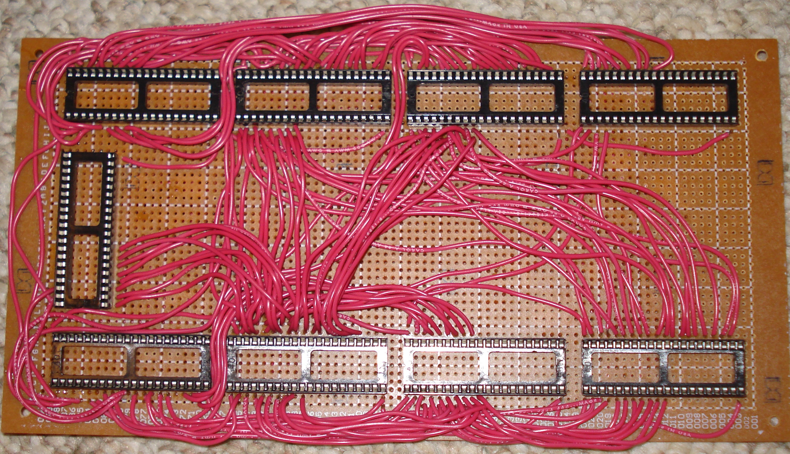
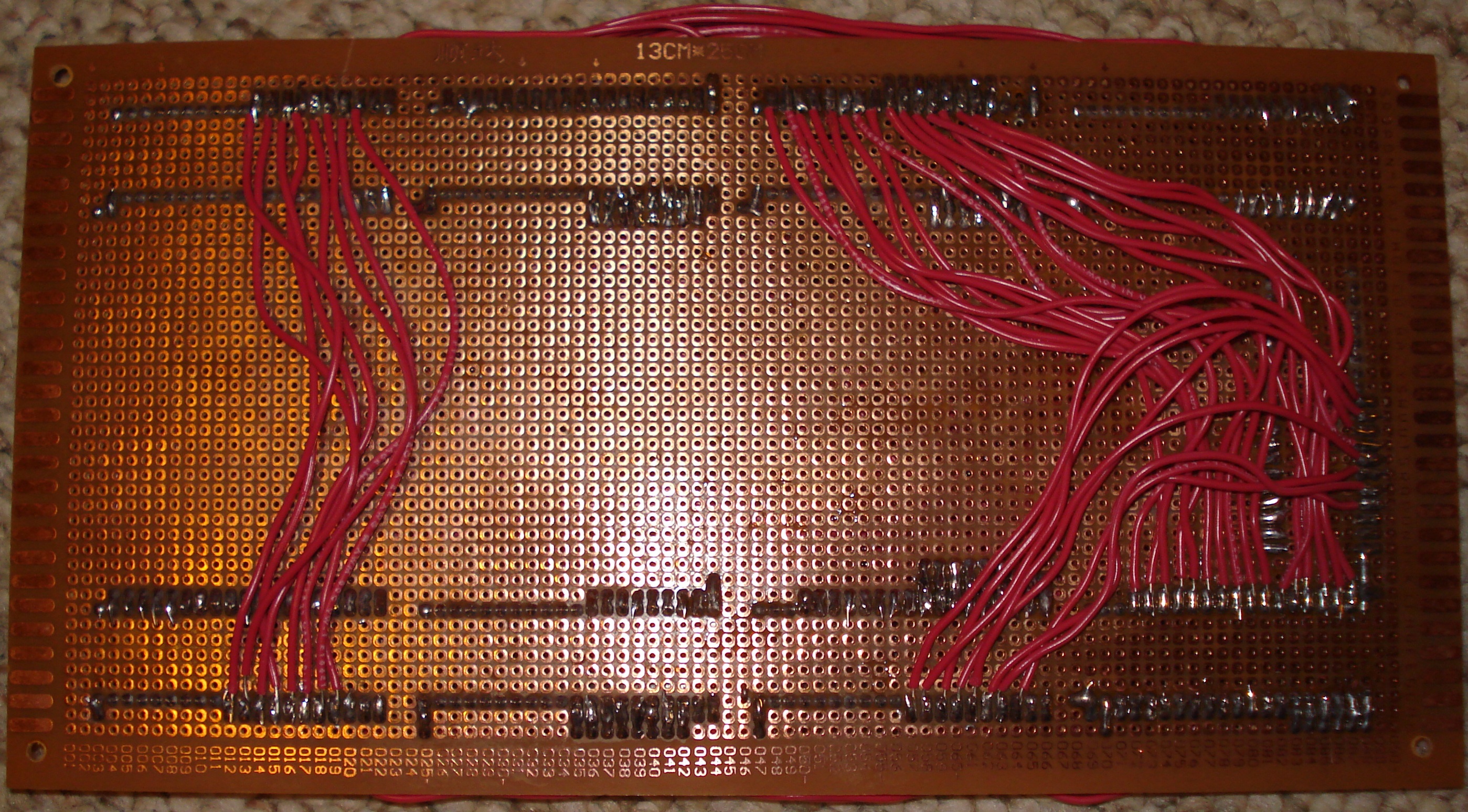
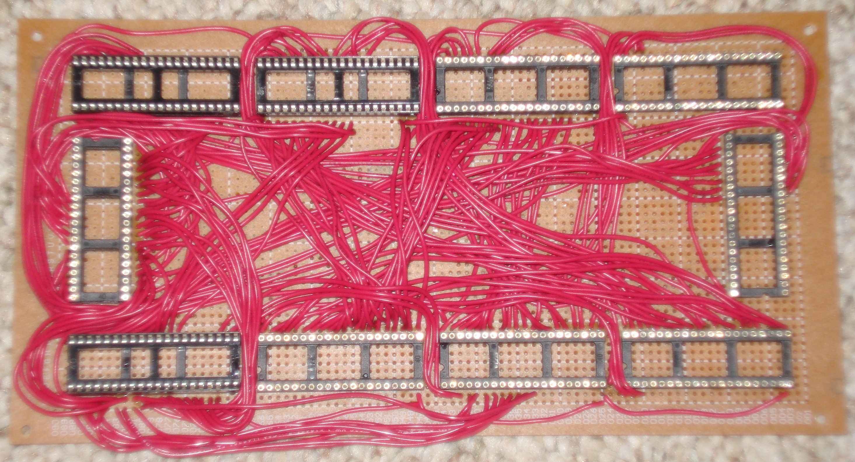
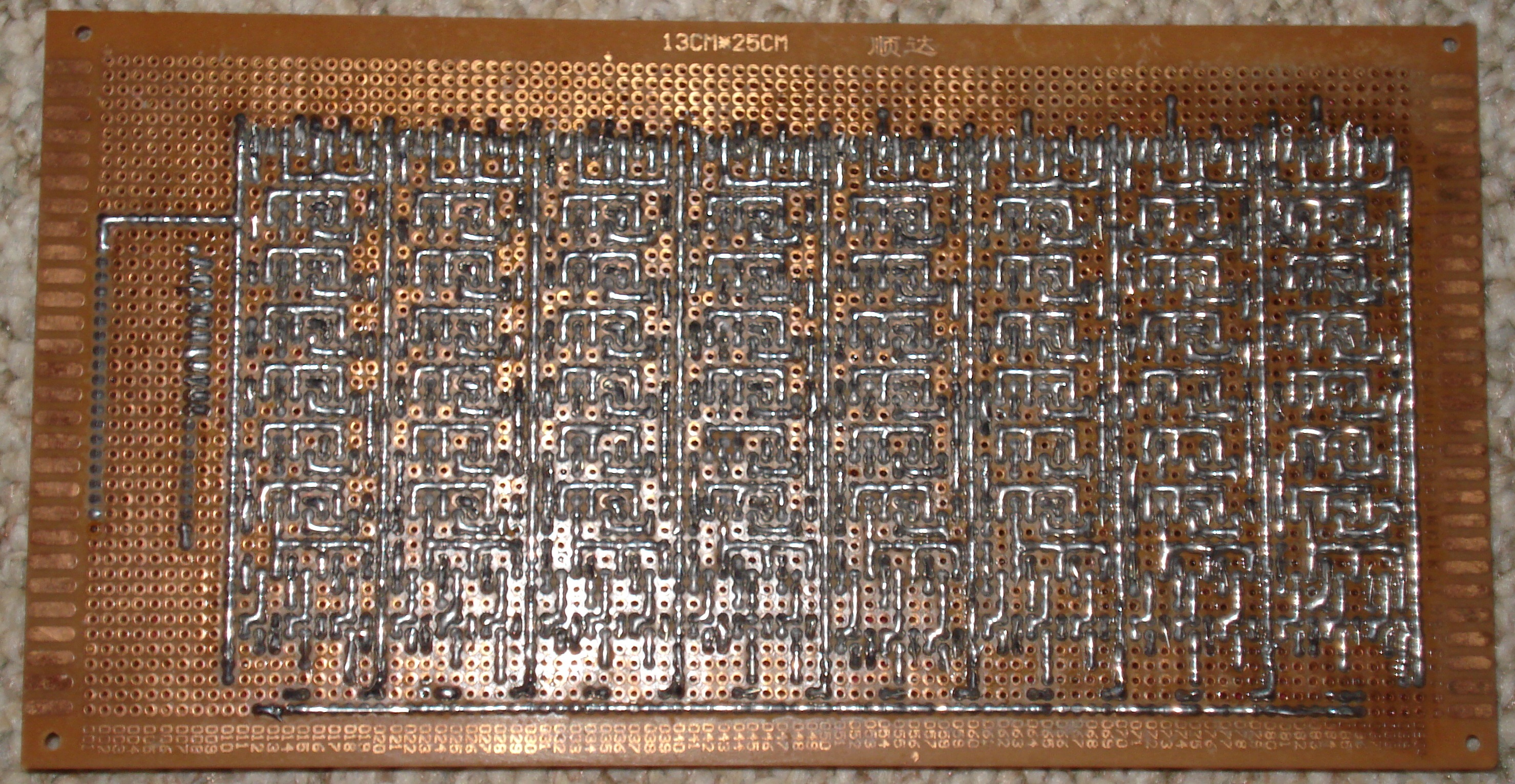
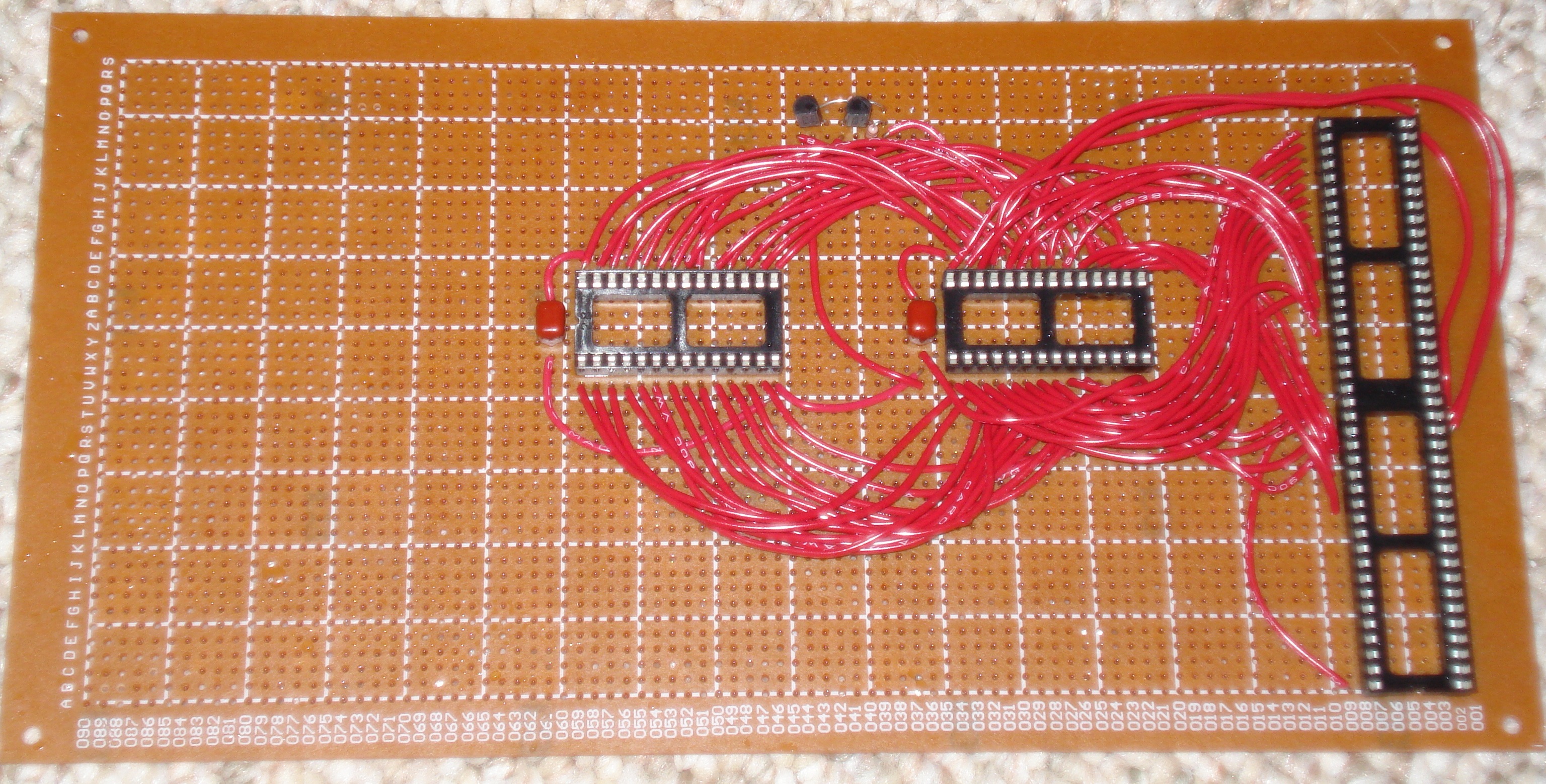
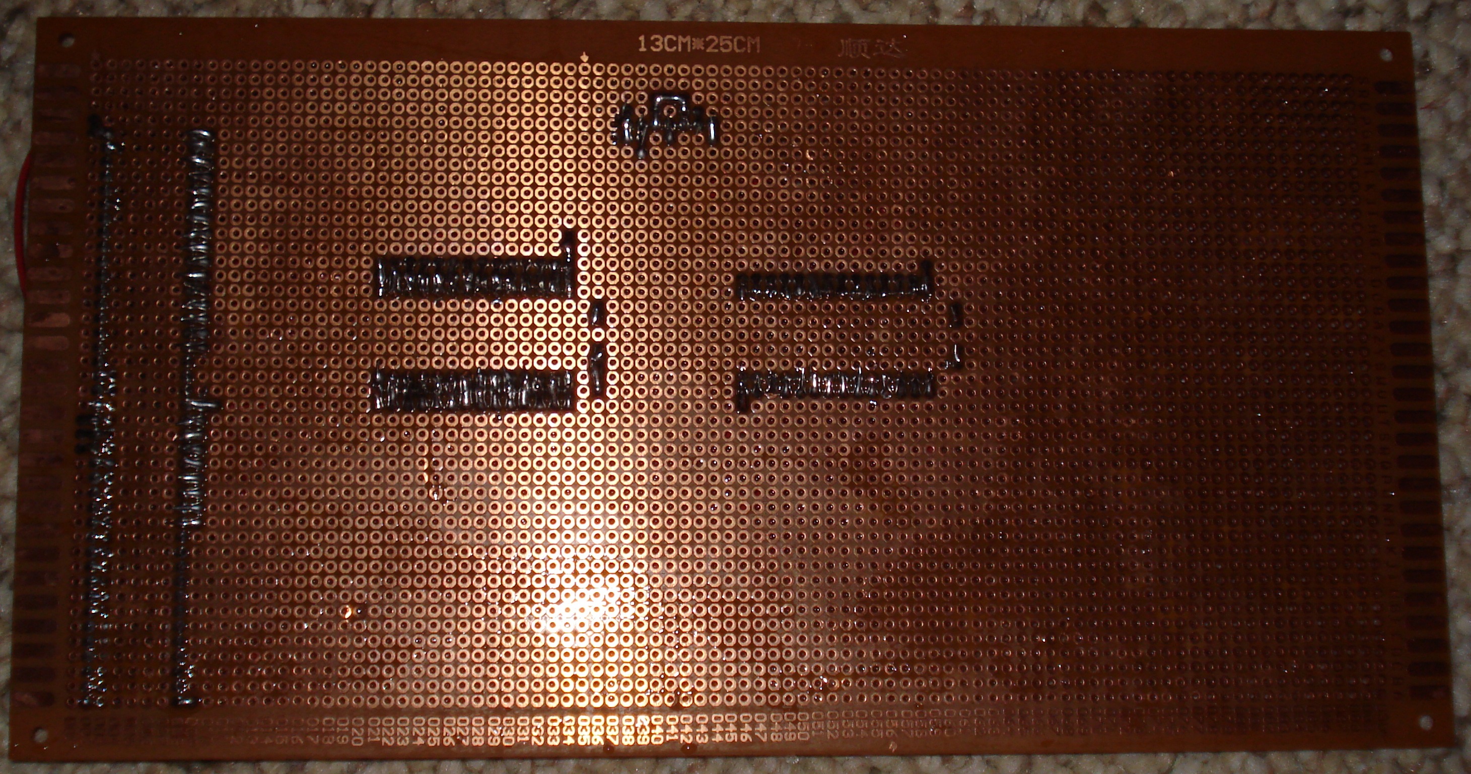
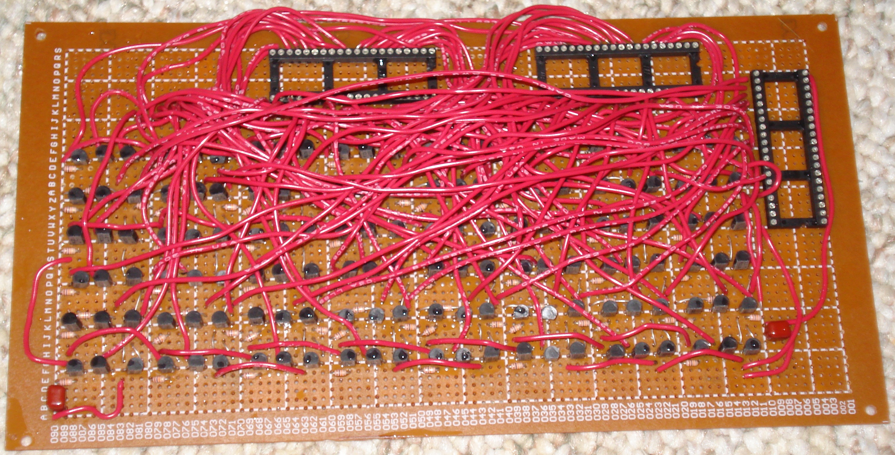
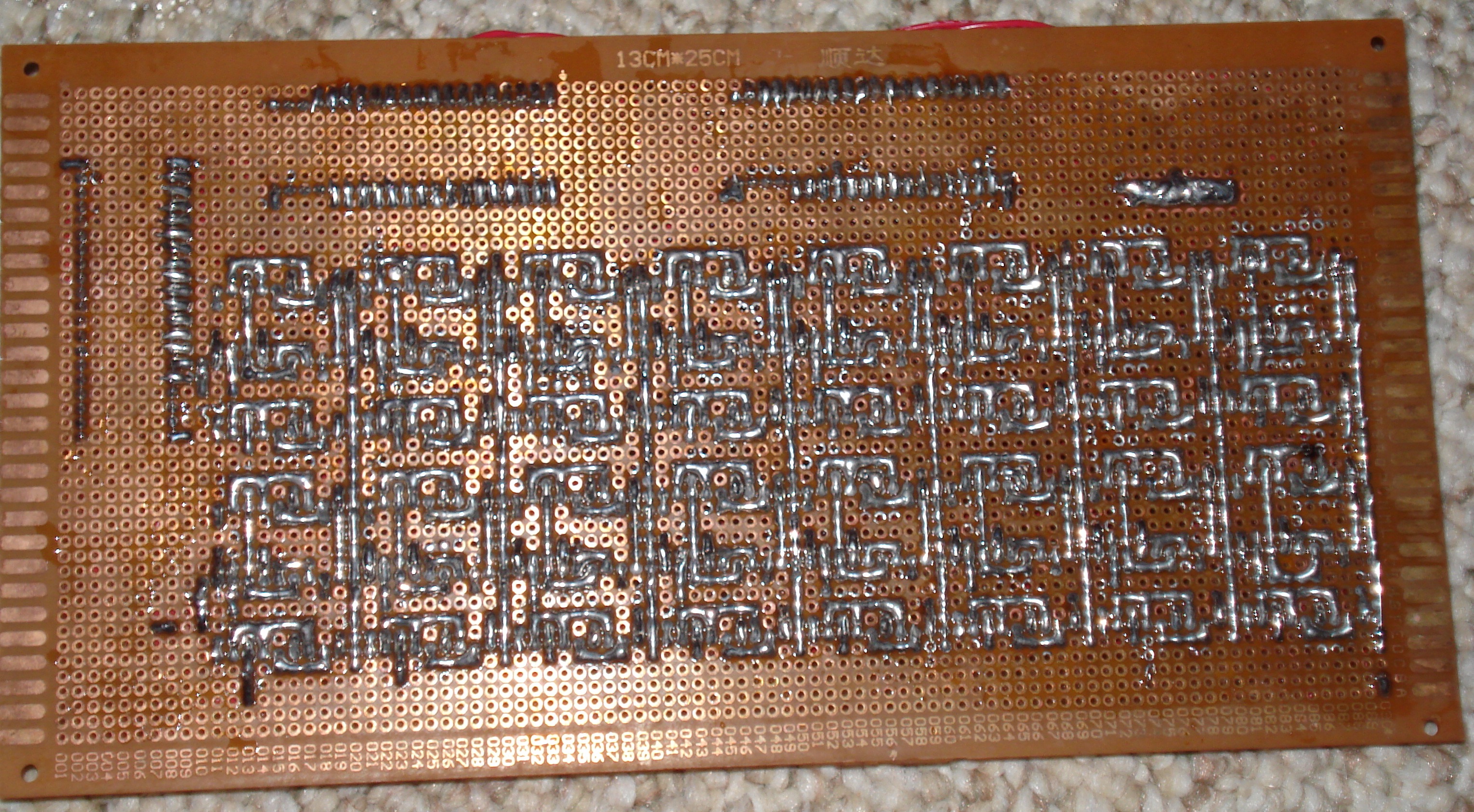
| Adder |
8-bit full adder with carry in and carry out. For now the carry in
will be tied to ground since the Q1 doesn't make use of it. Also
note that I goofed when wiring up the socket: GND and Vcc are in the
wrong places and the order of the bits is backwards. Add/Inc/Dec connector: GND NC NC NC NC NC NC NC NC NC Co S7 S6 S5 S4 S3 S2 S1 S0 Ci 1 2 3 4 5 6 7 8 9 10 11 12 13 14 15 16 17 18 19 20 40 39 38 37 36 35 34 33 32 31 30 29 28 27 26 25 24 23 22 21 NC NC NC B7 B6 B5 B4 B3 B2 B1 B0 A7 A6 A5 A4 A3 A2 A1 A0 Vcc |
216 transistors 144 10k resistors 1 socket |
Top Bottom |
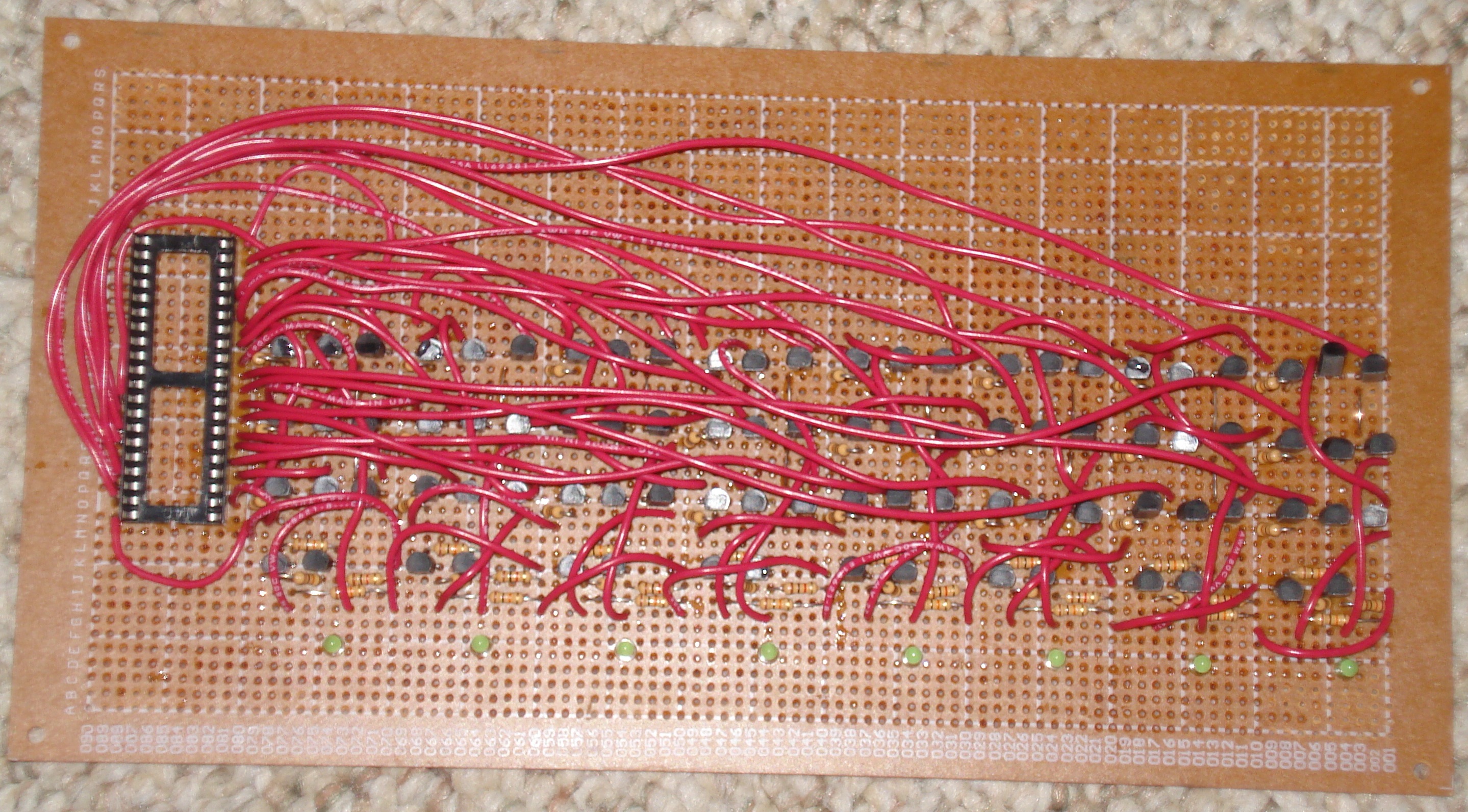
| A Register |
8-bit register with single input and open collector gated output. ALU connector: Vcc WR I0 I1 I2 I3 I4 I5 I6 I7 NC NC NC NC NC NC NC NC NC NC 1 2 3 4 5 6 7 8 9 10 11 12 13 14 15 16 17 18 19 20 40 39 38 37 36 35 34 33 32 31 30 29 28 27 26 25 24 23 22 21 RD O0 O1 O2 O3 O4 O5 O6 O7 NC NC NC NC NC NC NC NC NC NC GND |
104 transistors 64 10k resistors 8 1k resistors 8 LEDs 1 socket |
Top Bottom |
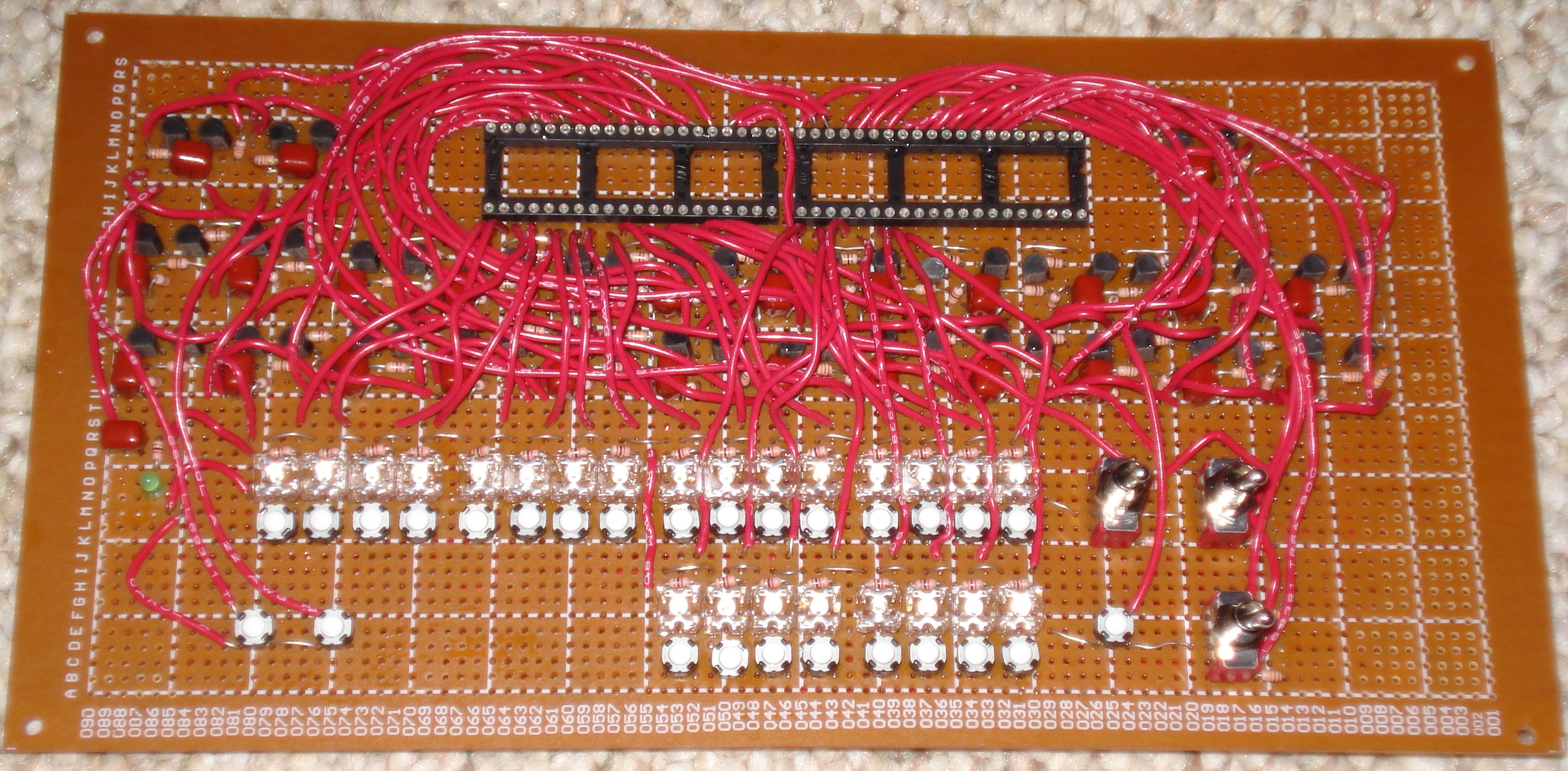
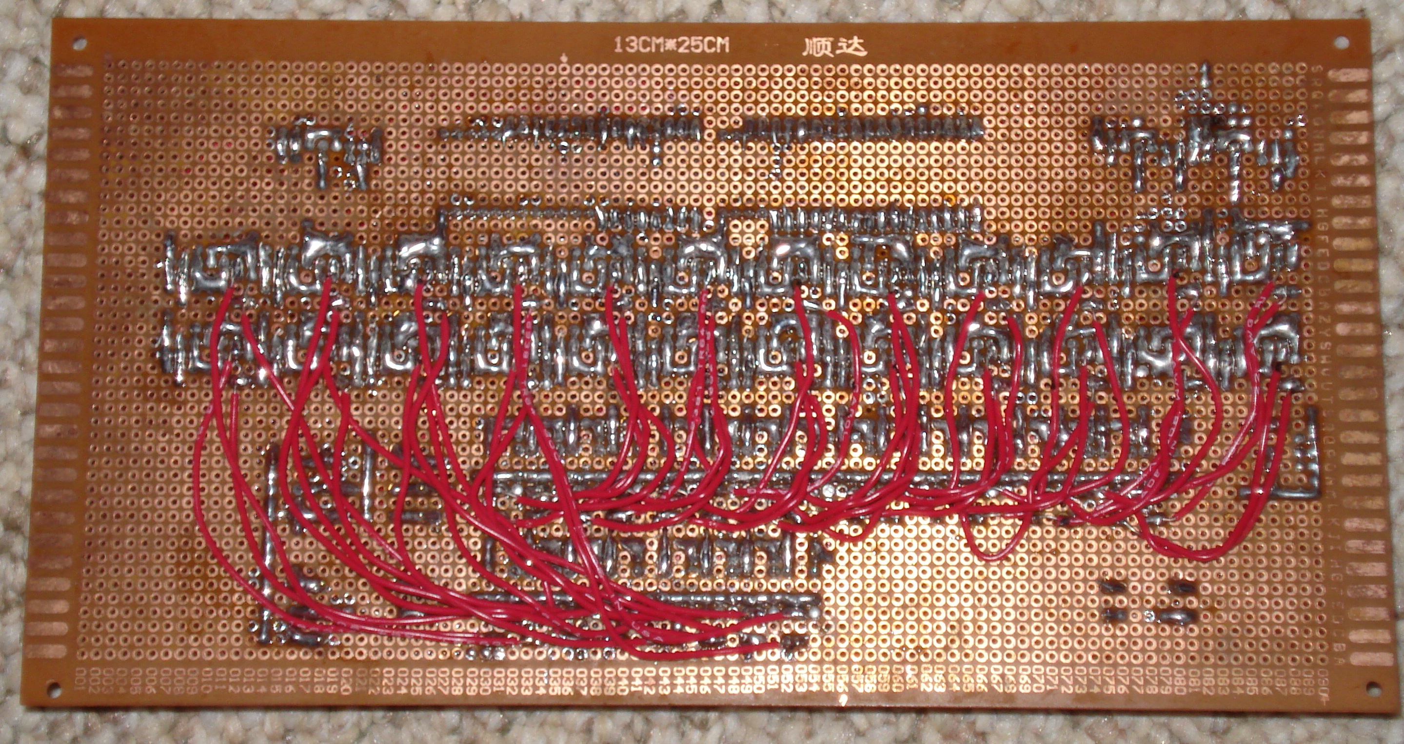
| B Register |
8-bit register with one positive/negative input, open collector
gated output (connected to input), and constant output (connected
to the first ALU source). ALU connector: Vcc RD WR D0 D1 D2 D3 D4 D5 D6 D7 ~D0 ~D1 ~D2 ~D3 ~D4 ~D5 ~D6 ~D7 NC 1 2 3 4 5 6 7 8 9 10 11 12 13 14 15 16 17 18 19 20 40 39 38 37 36 35 34 33 32 31 30 29 28 27 26 25 24 23 22 21 V0 V1 V2 V3 V4 V5 V6 V7 NC NC NC NC NC NC NC NC NC NC NC GND |
104 transistors 64 10k resistors 8 1k resistors 8 LEDs 1 socket |
Top Bottom |
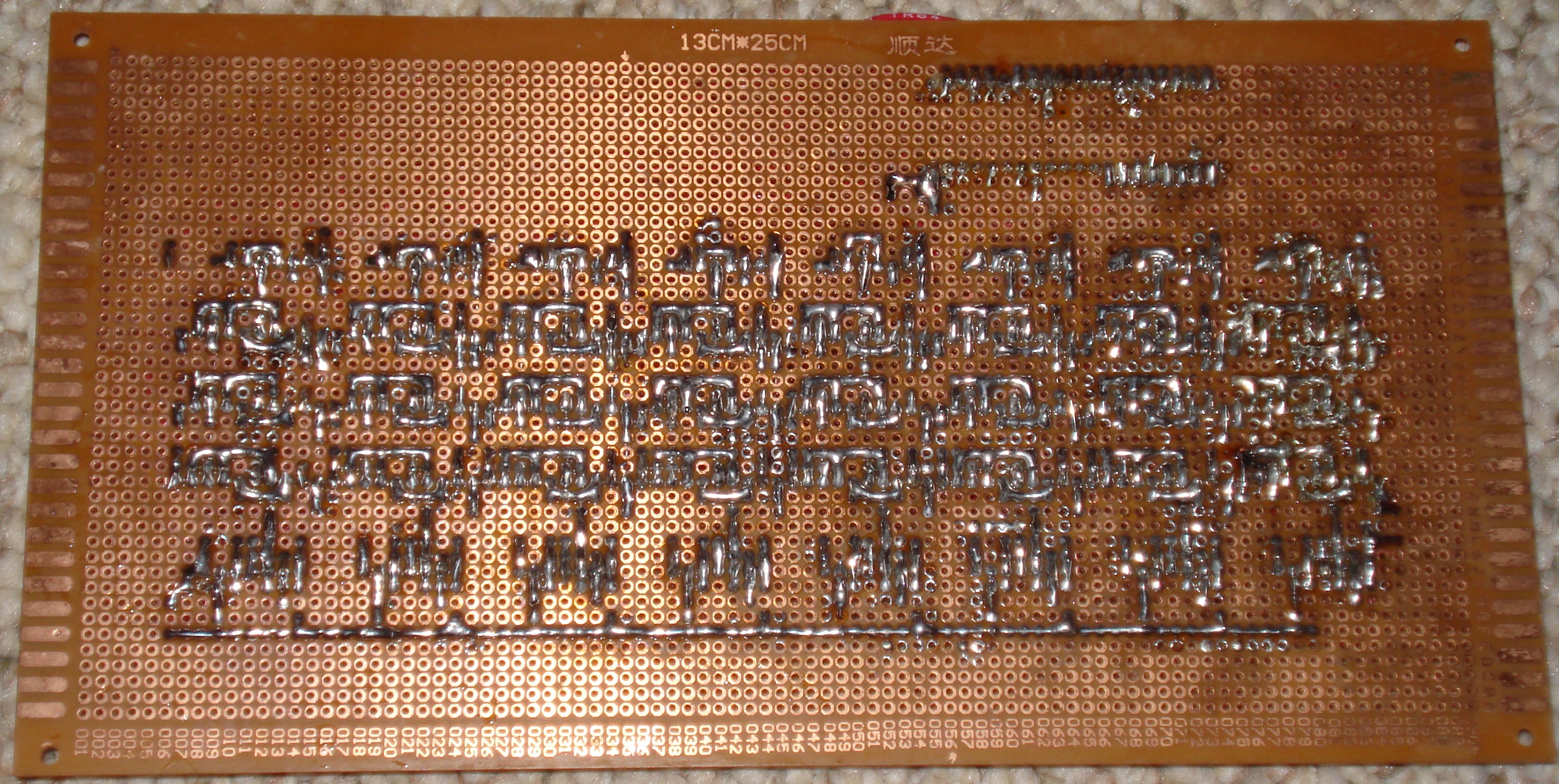
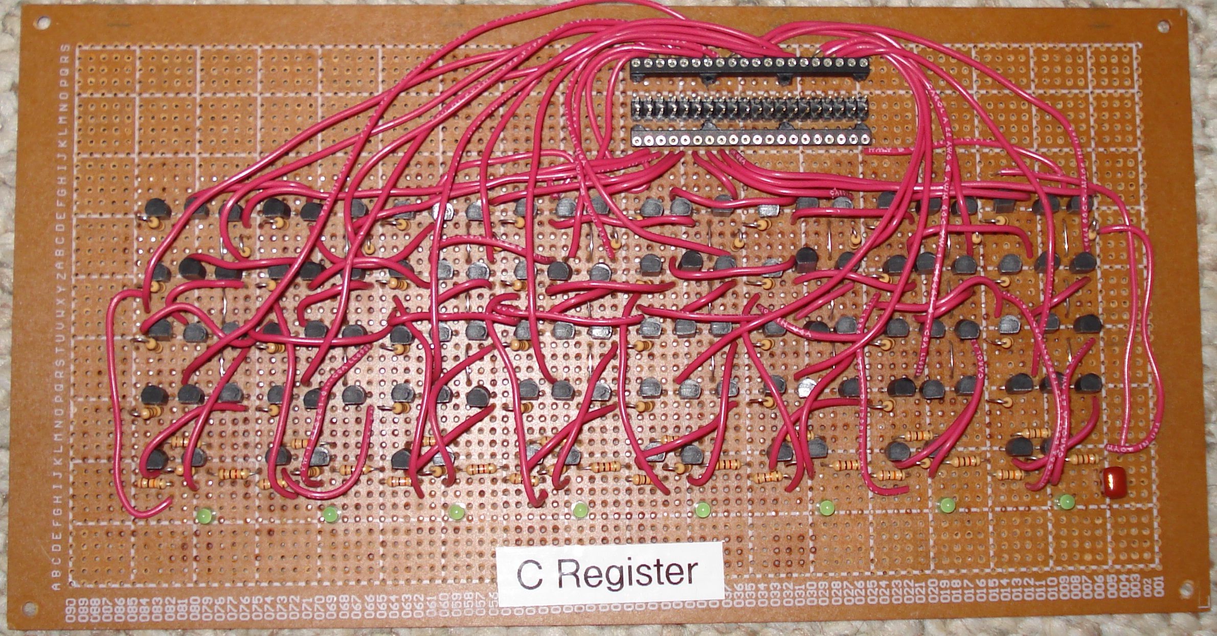
| C Register |
8-bit register with one positive/negative input, and two open
collector gated outputs. One of the outputs is connected to the
input. The other is used for the second ALU source, which is either
the C register (read enabled) or 1 (read disabled). ALU connector: Vcc RD WR D0 D1 D2 D3 D4 D5 D6 D7 ~D0 ~D1 ~D2 ~D3 ~D4 ~D5 ~D6 ~D7 NC 1 2 3 4 5 6 7 8 9 10 11 12 13 14 15 16 17 18 19 20 40 39 38 37 36 35 34 33 32 31 30 29 28 27 26 25 24 23 22 21 RO O0 O1 O2 O3 O4 O5 O6 O7 NC NC NC NC NC NC NC NC NC NC GND |
112 transistors 56 10k resistors 8 1k resistors 8 LEDs 1 socket |
Top Bottom |
| Shifter |
Left and right shifter with selectors. ALU connector: Vcc A0 A1 A2 A3 A4 A5 A6 A7 NC NC NC NC NC NC NC NC NC NC NC 1 2 3 4 5 6 7 8 9 10 11 12 13 14 15 16 17 18 19 20 40 39 38 37 36 35 34 33 32 31 30 29 28 27 26 25 24 23 22 21 SHL SHR O0 O1 O2 O3 O4 O5 O6 O7 CO NC NC NC NC NC NC NC NC GND |
68 transistors 34 10k resistors 1 socket |
N/A |
| AND/OR Unit |
AND and OR unit with selectors. ALU connector: Vcc A0 A1 A2 A3 A4 A5 A6 A7 B0 B1 B2 B3 B4 B5 B6 B7 NC NC NC 1 2 3 4 5 6 7 8 9 10 11 12 13 14 15 16 17 18 19 20 40 39 38 37 36 35 34 33 32 31 30 29 28 27 26 25 24 23 22 21 AND OR O0 O1 O2 O3 O4 O5 O6 O7 CO NC NC NC NC NC NC NC NC GND |
108 transistors 58 10k resistors 1 socket |
N/A |
| CLR/NOT Unit |
Clear/NOT unit with selectors. ALU connector: Vcc I0 I1 I2 I3 I4 I5 I6 I7 NC NC NC NC NC NC NC NC NC NC NC 1 2 3 4 5 6 7 8 9 10 11 12 13 14 15 16 17 18 19 20 40 39 38 37 36 35 34 33 32 31 30 29 28 27 26 25 24 23 22 21 CLR NOT O0 O1 O2 O3 O4 O5 O6 O7 CO NC NC NC NC NC NC NC NC GND |
67 transistors 42 10k resistors 1 socket |
N/A |
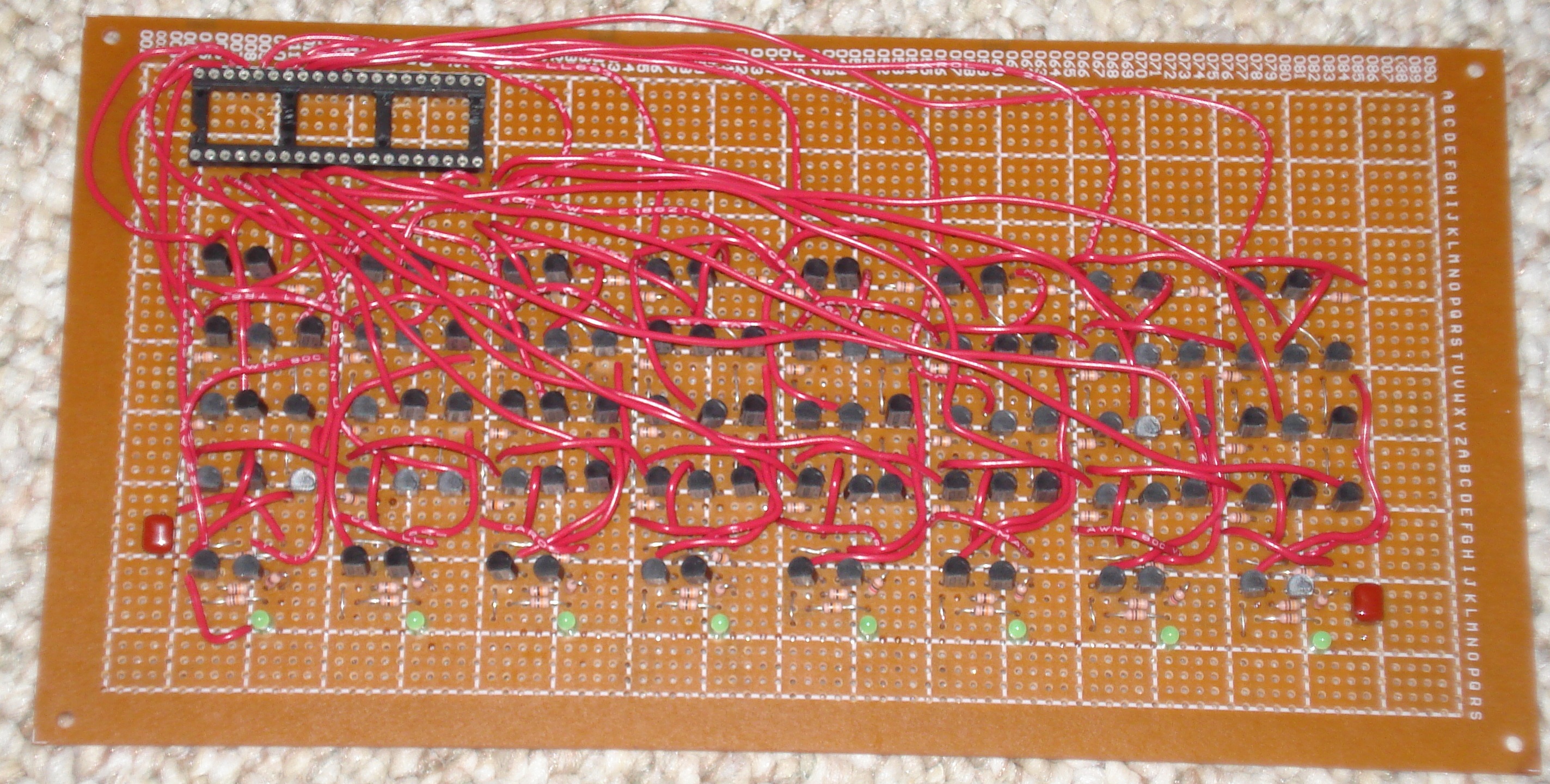
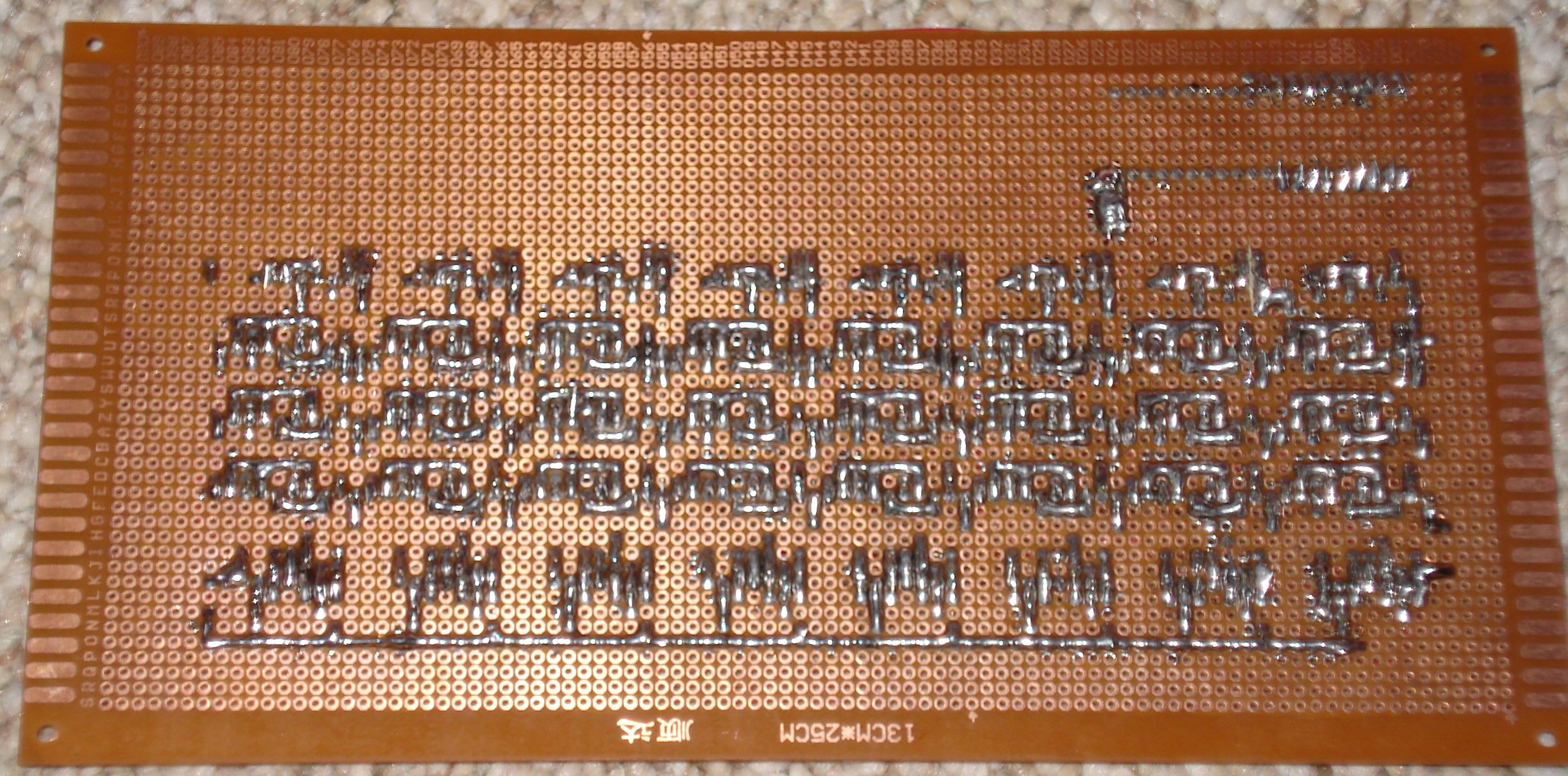
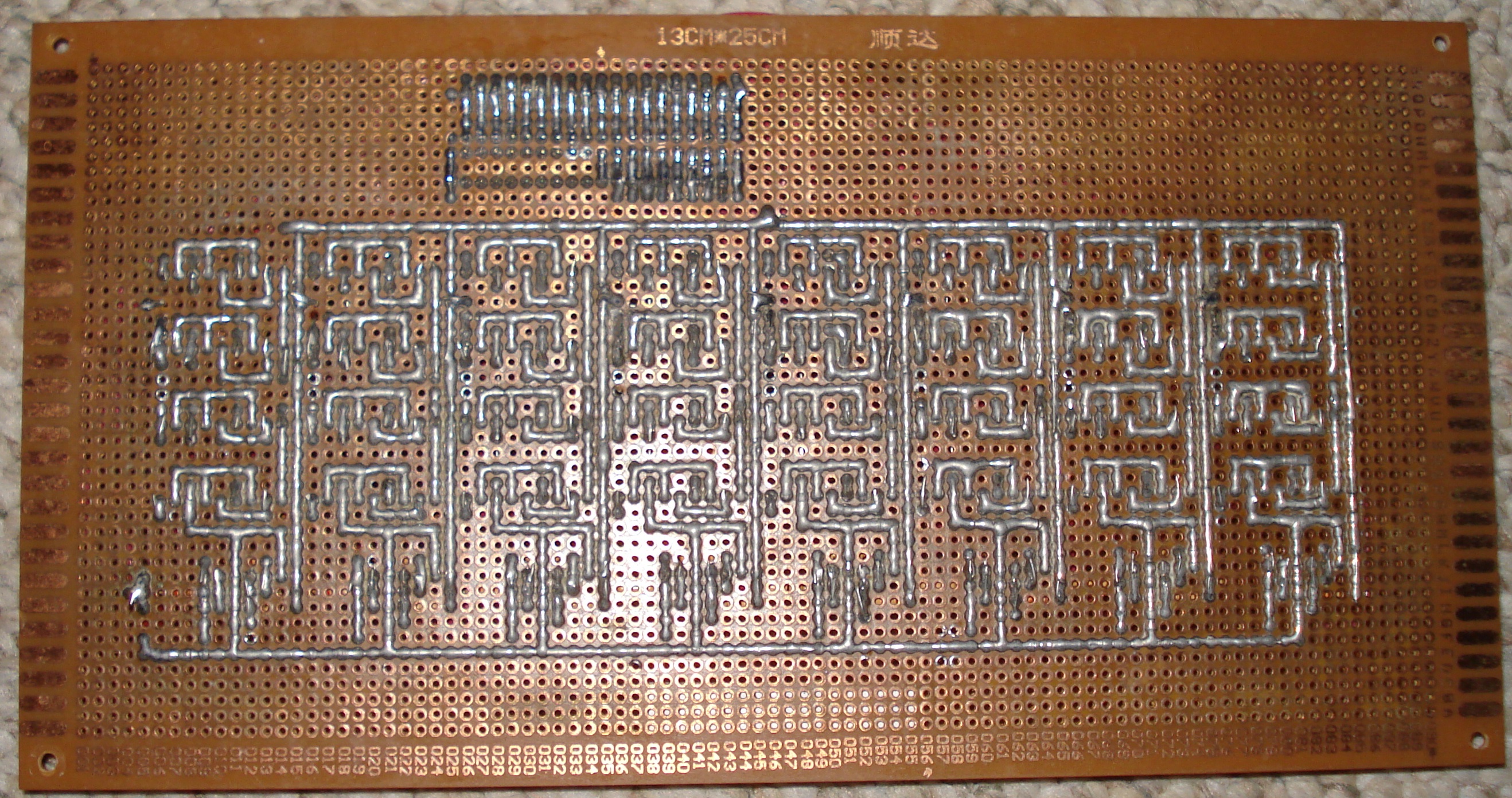
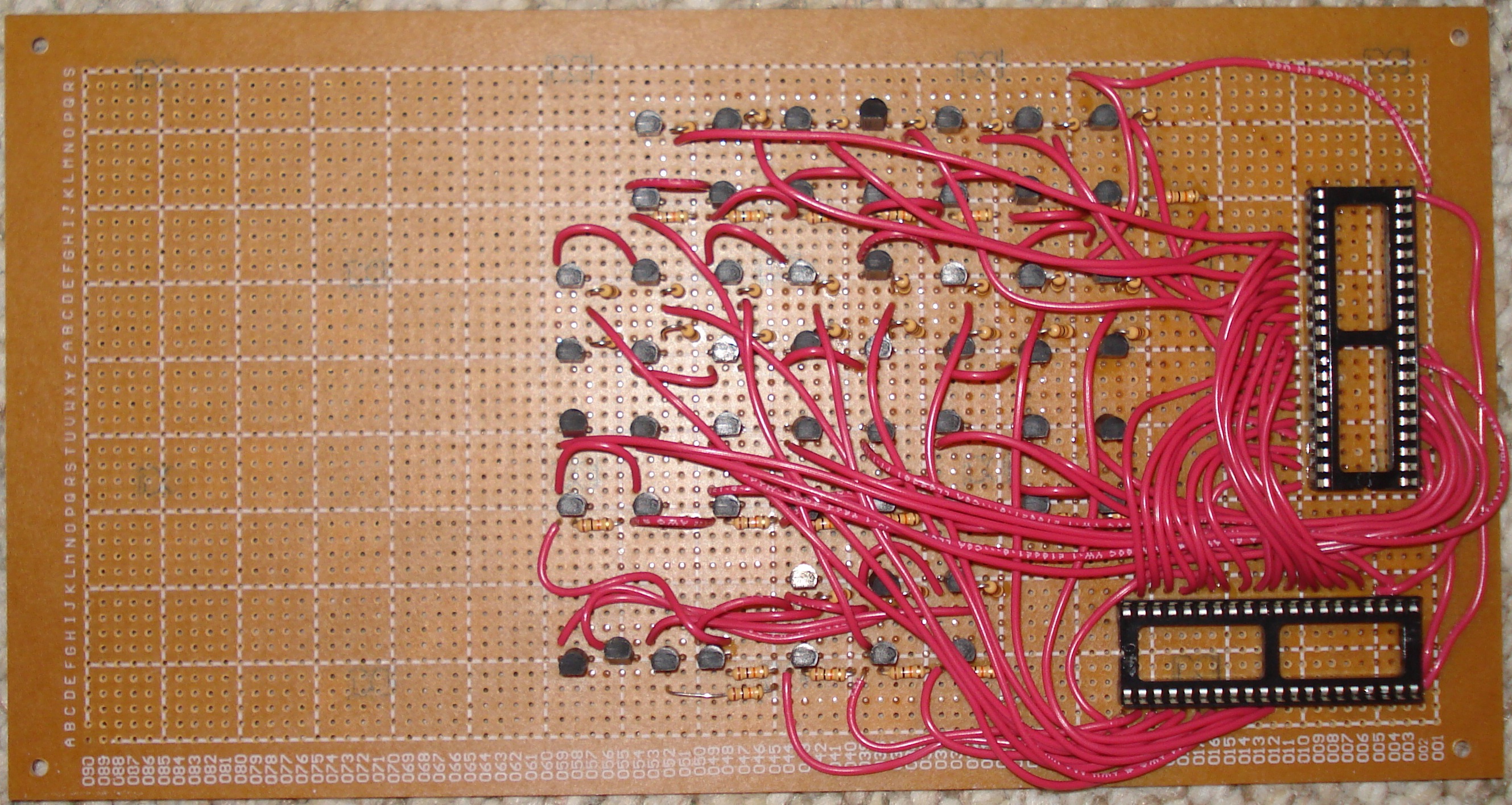
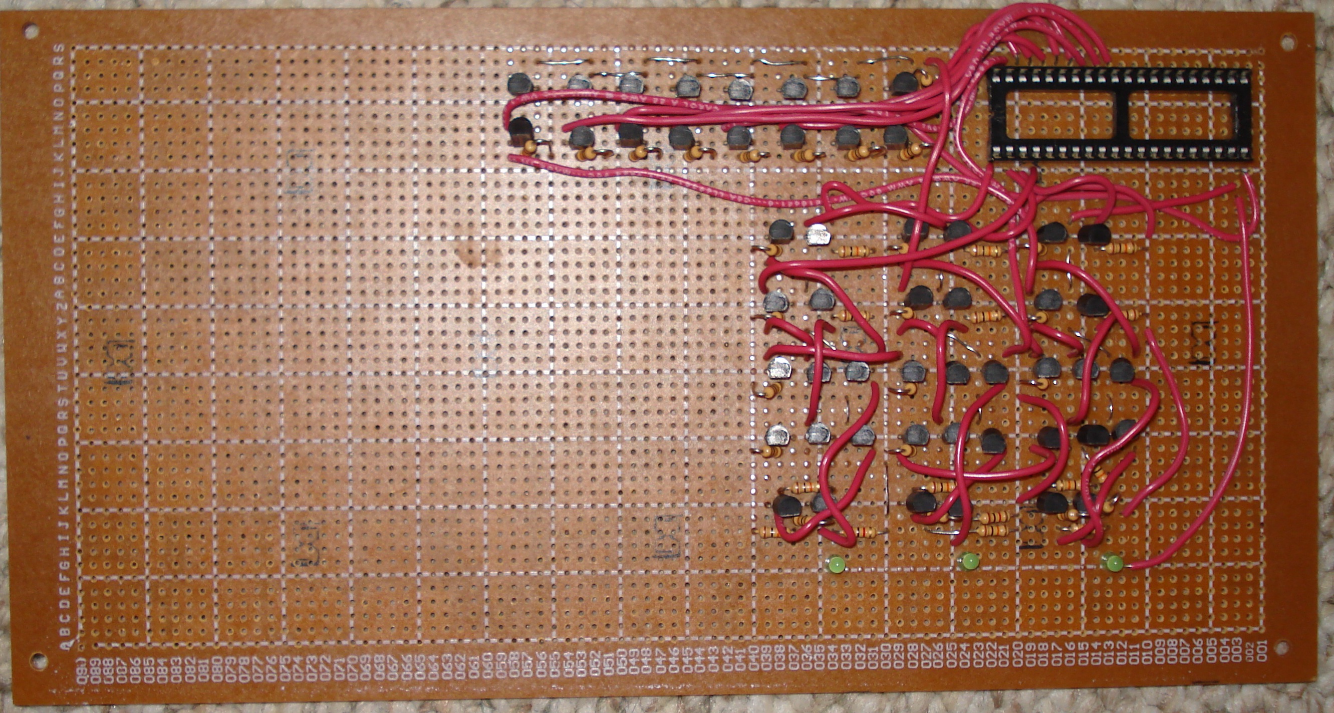
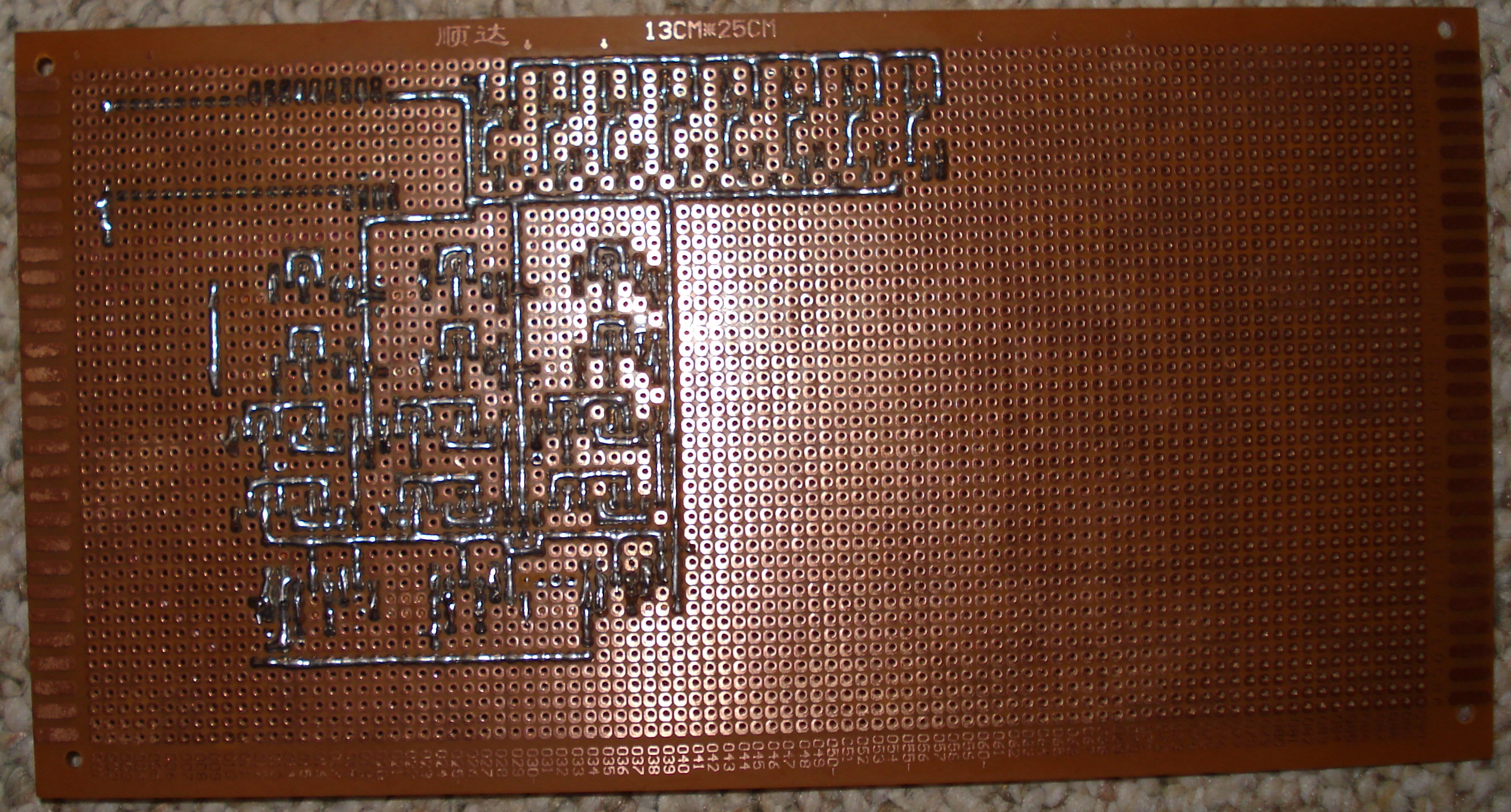
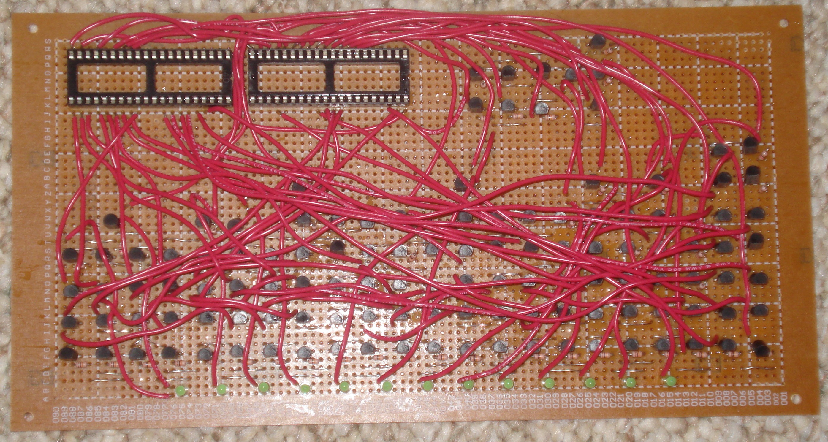
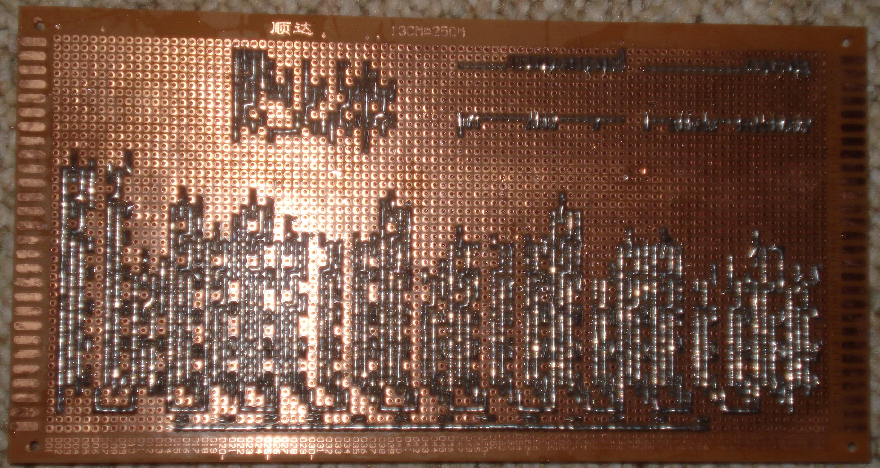
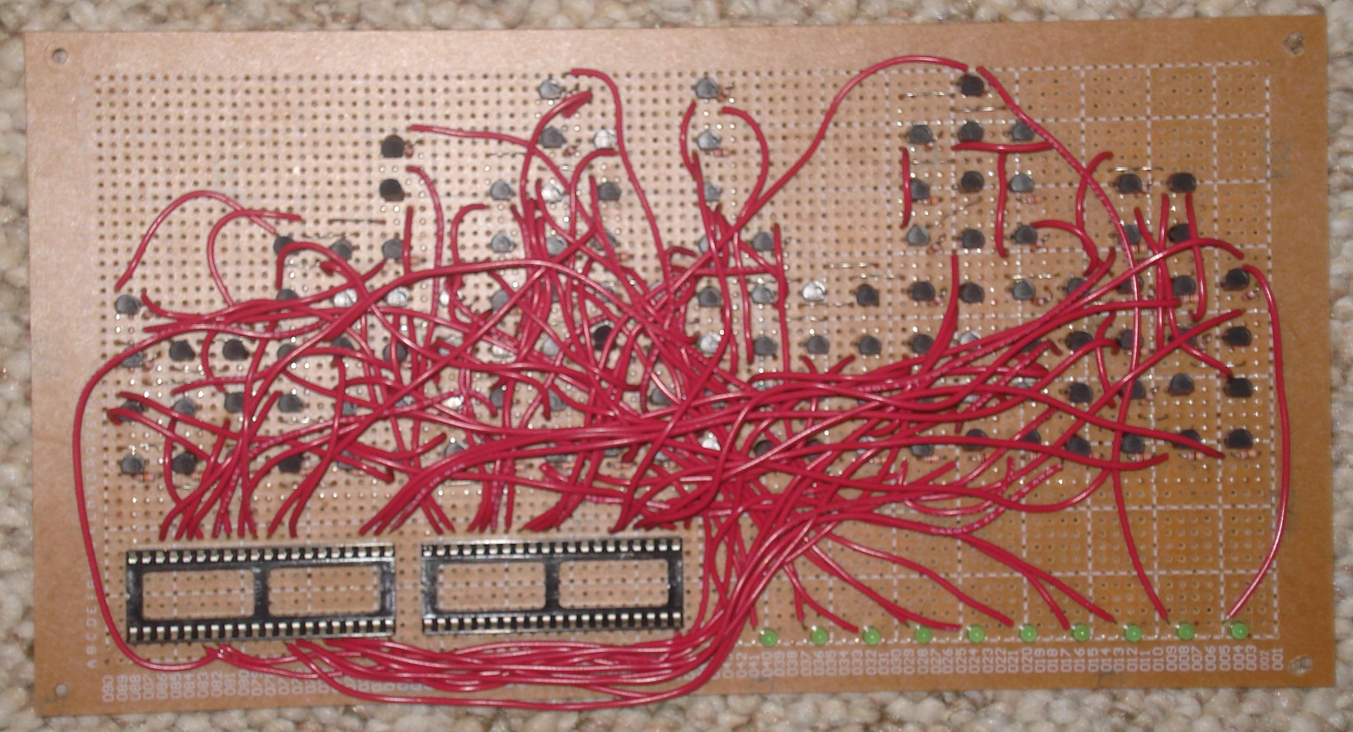
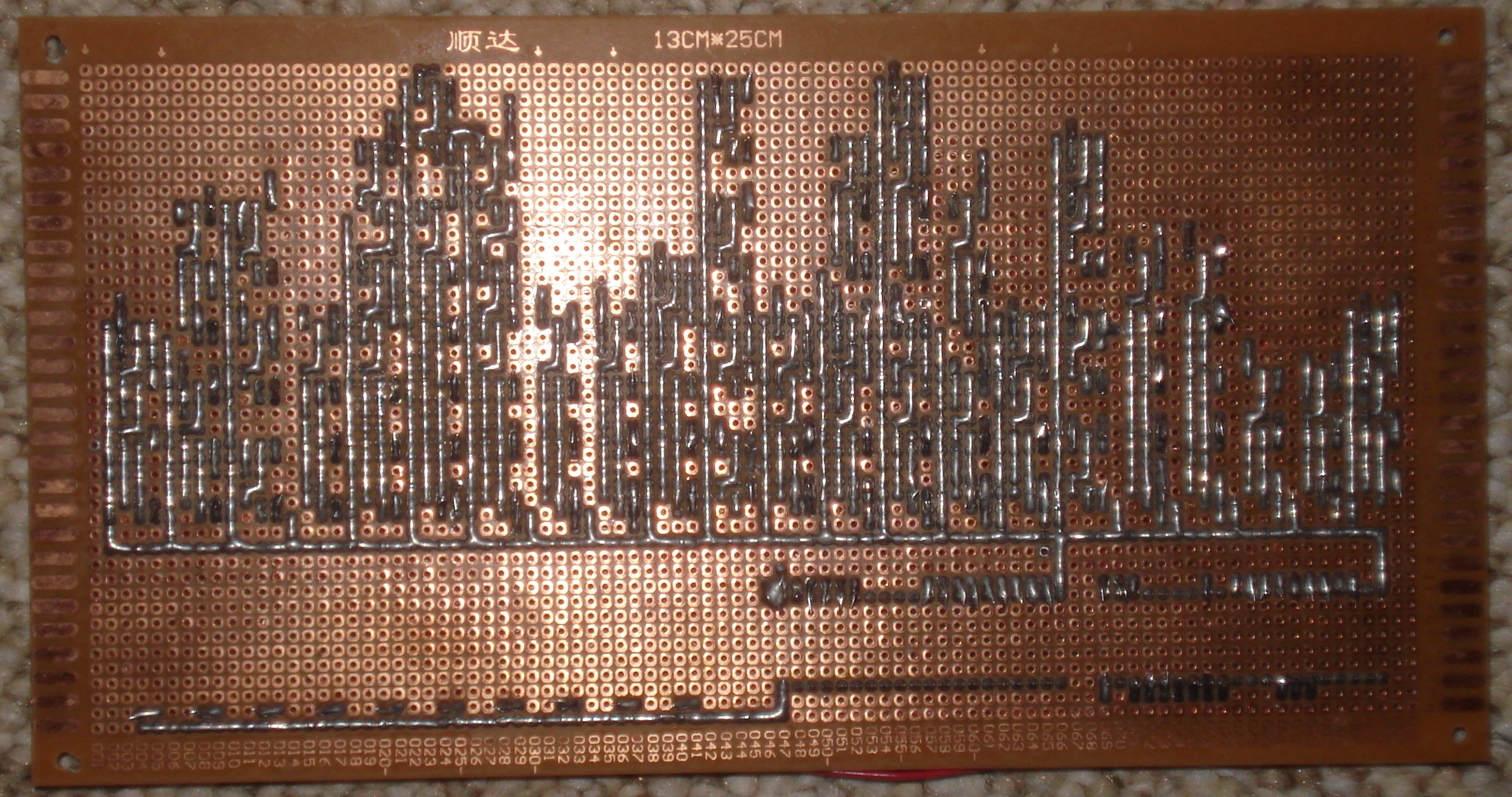
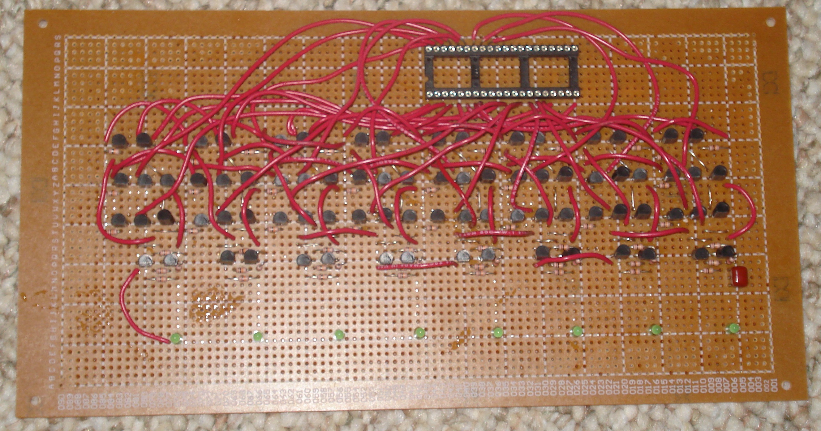
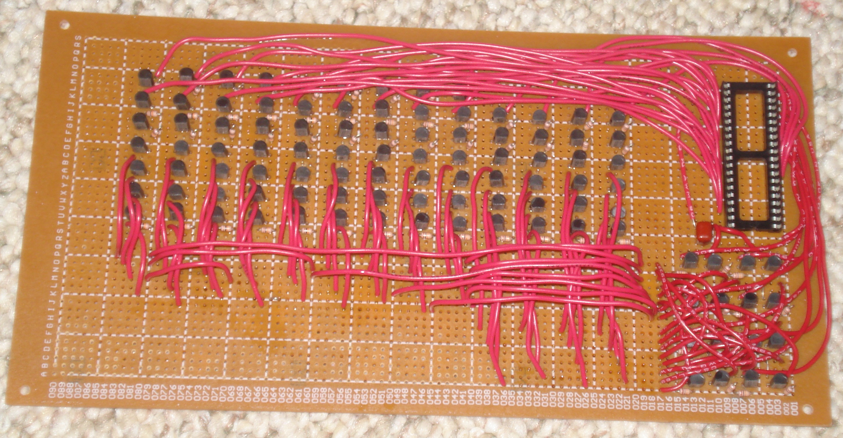
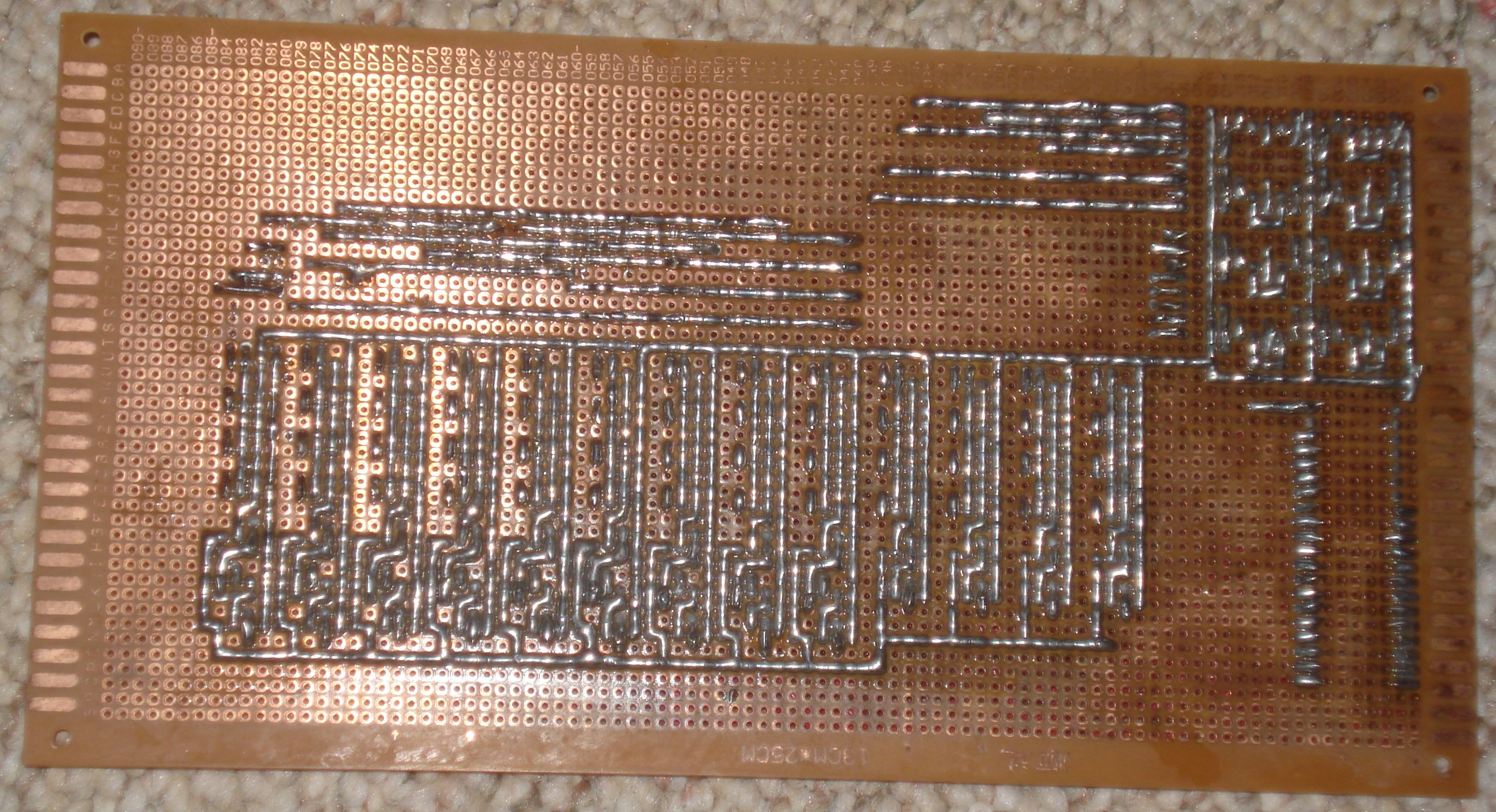
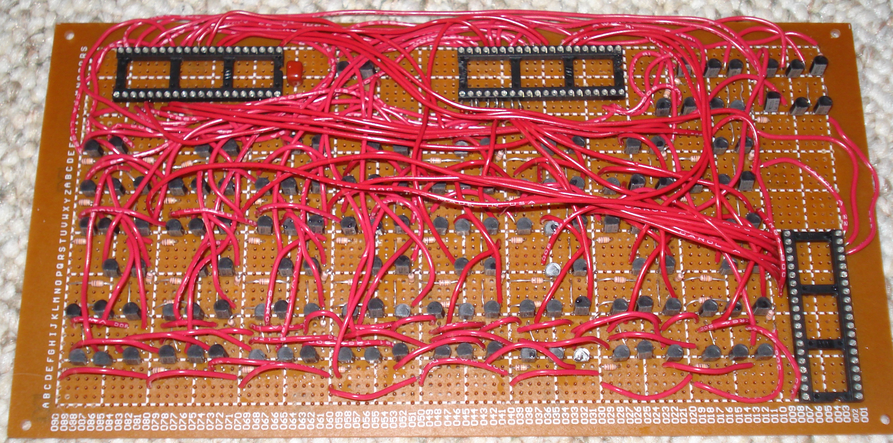
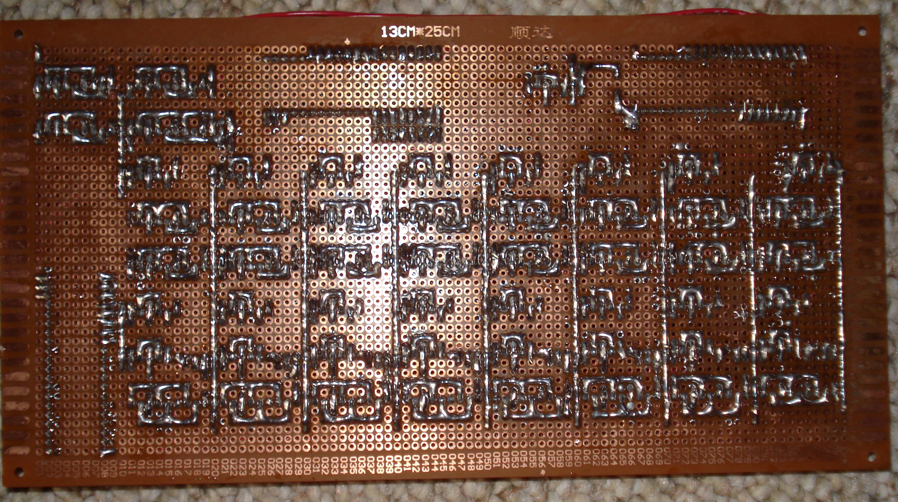
| Add/Inc/Dec Unit |
Add/Increment/Decrement unit with selectors. ALU connector: Vcc B0 B1 B2 B3 B4 B5 B6 B7 C0 C1 C2 C3 C4 C5 C6 C7 CO RC NC 1 2 3 4 5 6 7 8 9 10 11 12 13 14 15 16 17 18 19 20 40 39 38 37 36 35 34 33 32 31 30 29 28 27 26 25 24 23 22 21 ADD INC DEC O0 O1 O2 O3 O4 O5 O6 O7 NC NC NC NC NC NC NC NC GNDAdder connector: GND NC NC NC NC NC NC NC NC NC Co S7 S6 S5 S4 S3 S2 S1 S0 GND 1 2 3 4 5 6 7 8 9 10 11 12 13 14 15 16 17 18 19 20 40 39 38 37 36 35 34 33 32 31 30 29 28 27 26 25 24 23 22 21 NC NC NC B7 B6 B5 B4 B3 B2 B1 B0 A7 A6 A5 A4 A3 A2 A1 A0 Vcc |
77 transistors 56 10k resistors 2 sockets |
Top Bottom |
| Flags |
Zero detect and CF, ZF, and NF registers. Each register has
a single input with a constant output. A single write line
controls the registers (the same write line that controls the
A register). The input is connected to the input to the A
register. ALU connector: Vcc WR A0 A1 A2 A3 A4 A5 A6 A7 NC NC NC NC NC NC NC NC NC NC 1 2 3 4 5 6 7 8 9 10 11 12 13 14 15 16 17 18 19 20 40 39 38 37 36 35 34 33 32 31 30 29 28 27 26 25 24 23 22 21 CO ZO NO CI NC NC NC NC NC NC NC NC NC NC NC NC NC NC NC GND |
52 transistors 36 10k resistors 3 1k resistors 3 LEDs 1 socket |
Top Bottom |
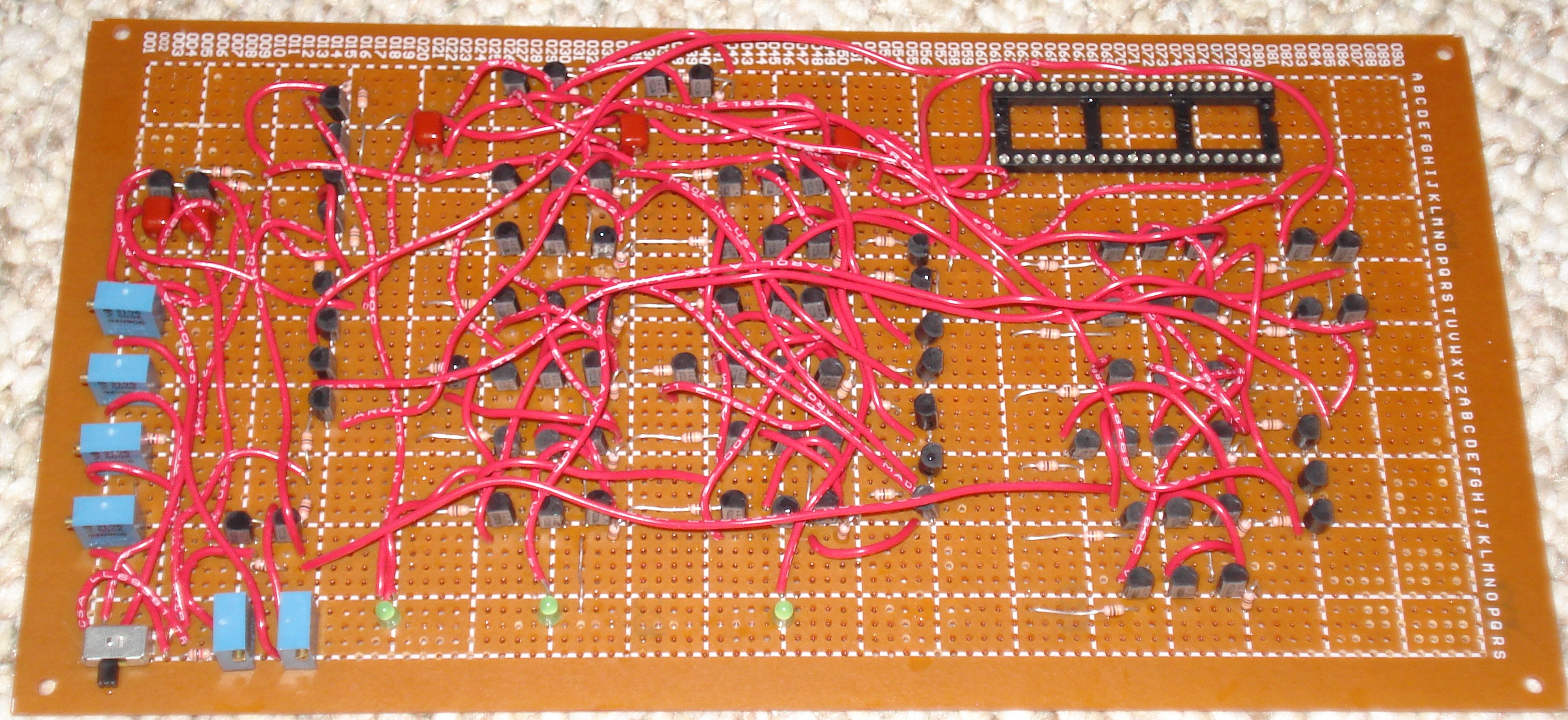
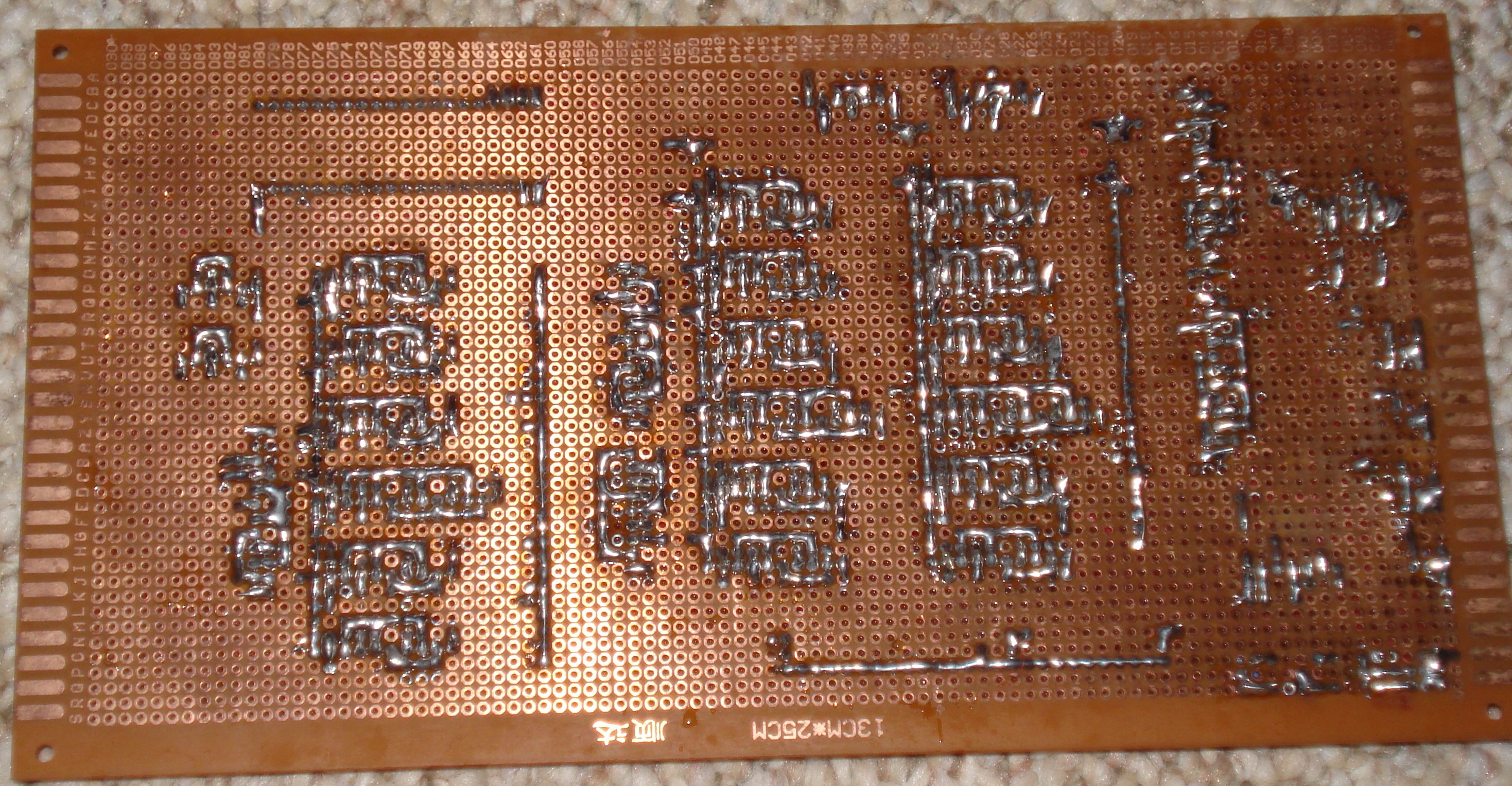
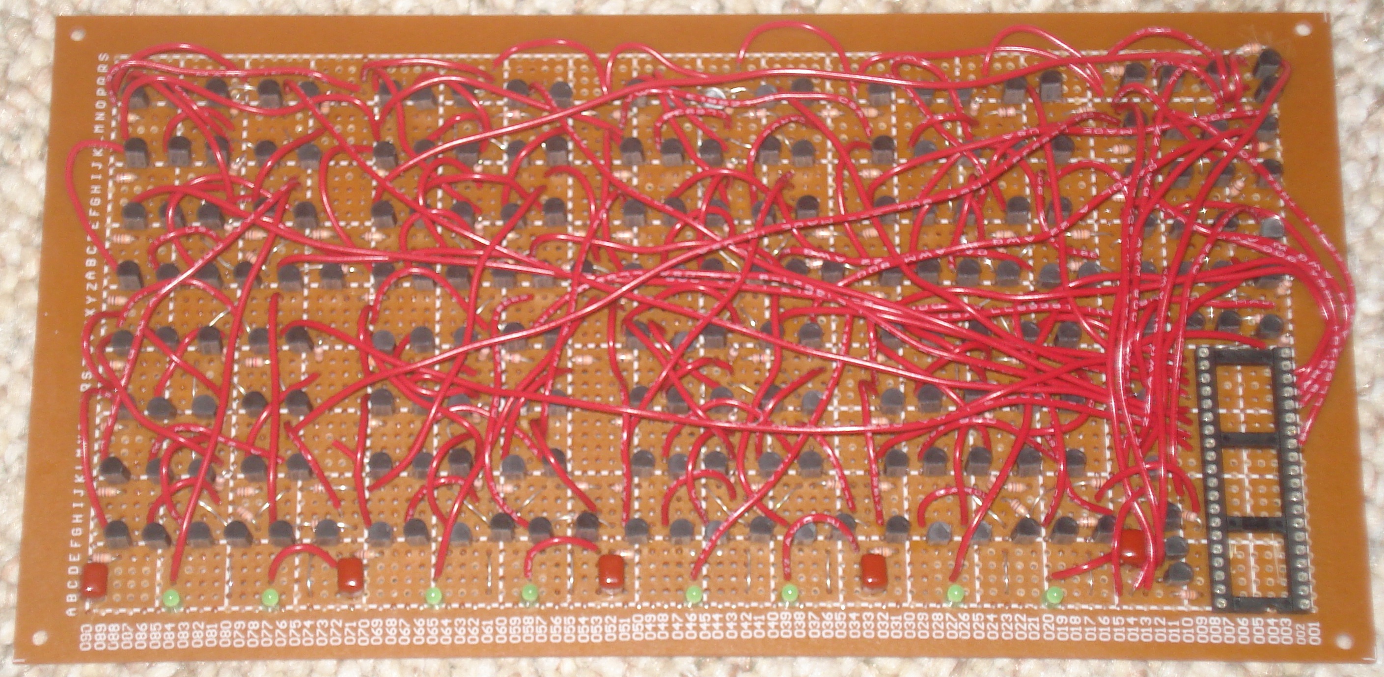
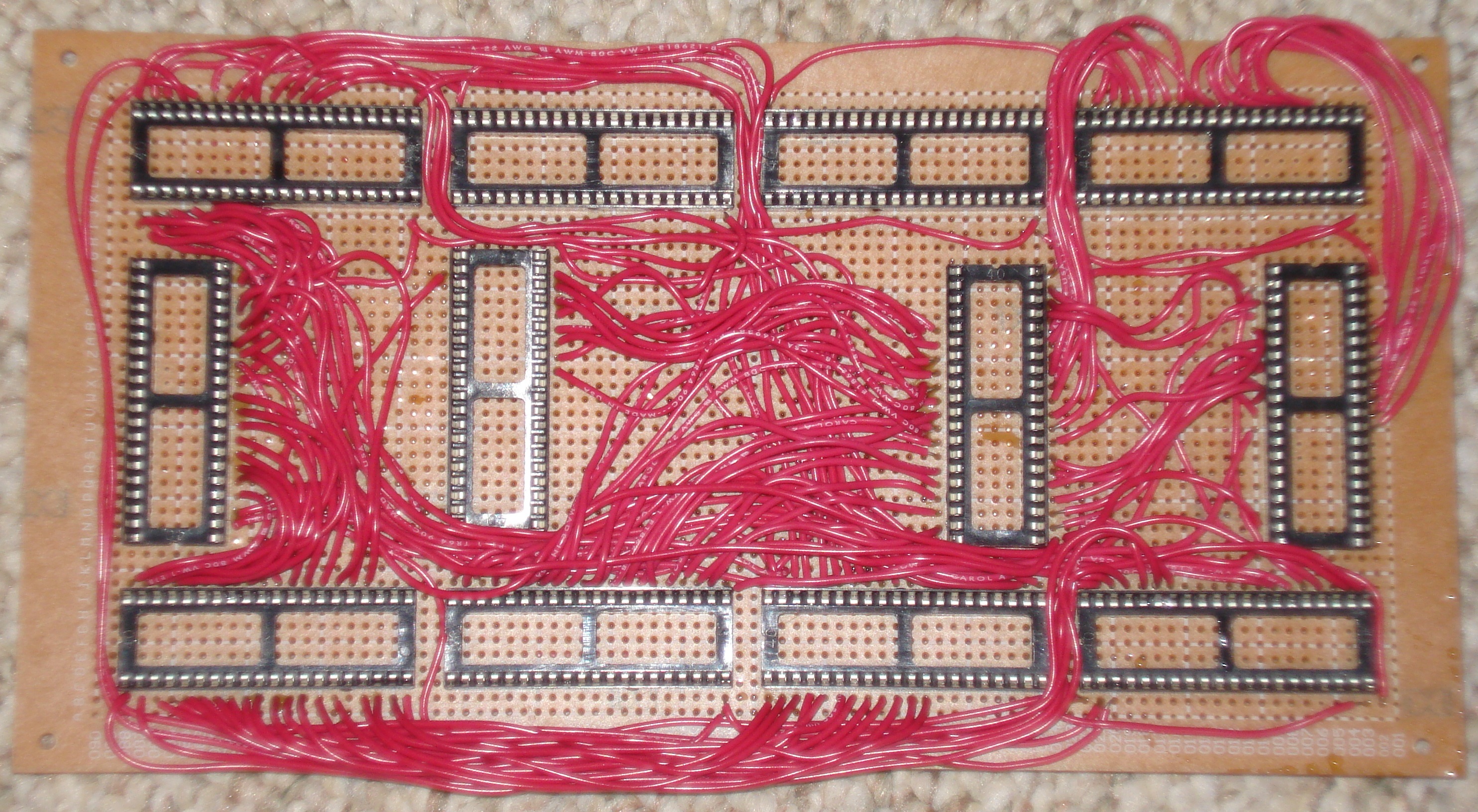
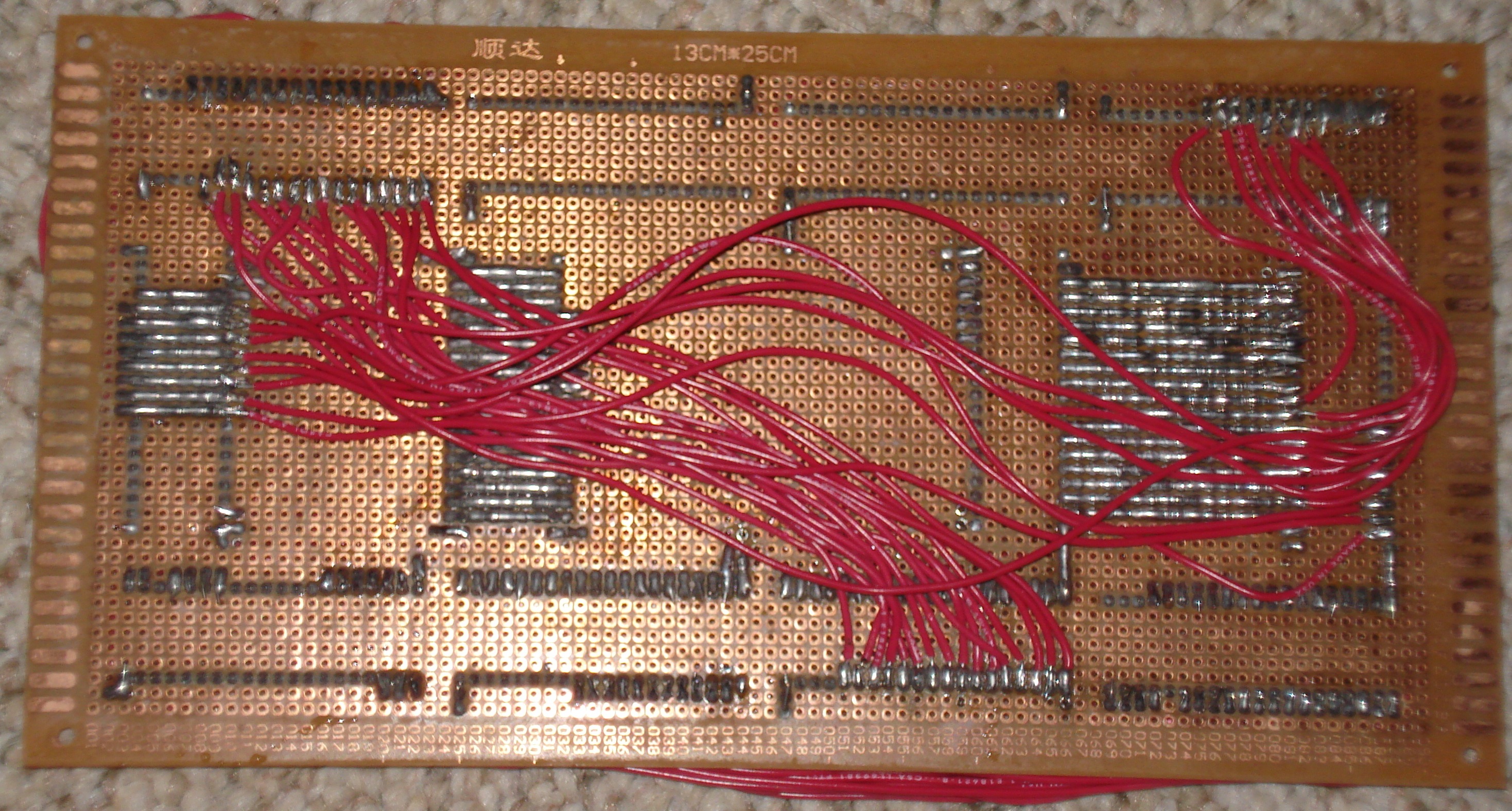
| ALU |
ALU board. This connects all the ALU modules together. System connector: Vcc D0 D1 D2 D3 D4 D5 D6 D7 ~D0 ~D1 ~D2 ~D3 ~D4 ~D5 ~D6 ~D7 NC NC NC 1 2 3 4 5 6 7 8 9 10 11 12 13 14 15 16 17 18 19 20 40 39 38 37 36 35 34 33 32 31 30 29 28 27 26 25 24 23 22 21 WA RA WB RB WC RC F0 F1 F2 F3 F4 F5 F6 F7 F8 NC CF NF ZF GND |
9 sockets |
Top Bottom Layout |
Control Modules
| Module | Description | Parts | Images |
|---|---|---|---|
| Clock Generator |
Clock phase generator. Control connector: Vcc RST HLT STP NC NC NC NC NC NC NC NC NC NC NC NC NC NC NC NC 1 2 3 4 5 6 7 8 9 10 11 12 13 14 15 16 17 18 19 20 40 39 38 37 36 35 34 33 32 31 30 29 28 27 26 25 24 23 22 21 SC WC NC NC NC NC NC NC NC NC NC NC NC NC NC NC NC NC NC GND |
87 transistors 48 10k resistors 8 1k resistors 3 LEDs 5 .47uF capacitors 5 500k trimmer resistors 1 500 ohm trimmer resistor 1 DPDT switch 1 socket |
Top Bottom |
| State Machine |
State machine and next state logic. Control connector: Vcc RST SC C0 C1 C2 C3 F8 NC NC NC NC NC NC NC NC NC NC NC NC 1 2 3 4 5 6 7 8 9 10 11 12 13 14 15 16 17 18 19 20 40 39 38 37 36 35 34 33 32 31 30 29 28 27 26 25 24 23 22 21 S0 S1 S2 S3 S4 S5 S6 S7 NC NC NC NC NC NC NC NC NC NC NC GND |
198 transistors ? 10k resistors 8 1k resistors 8 LEDs 1 socket |
Top Bottom |
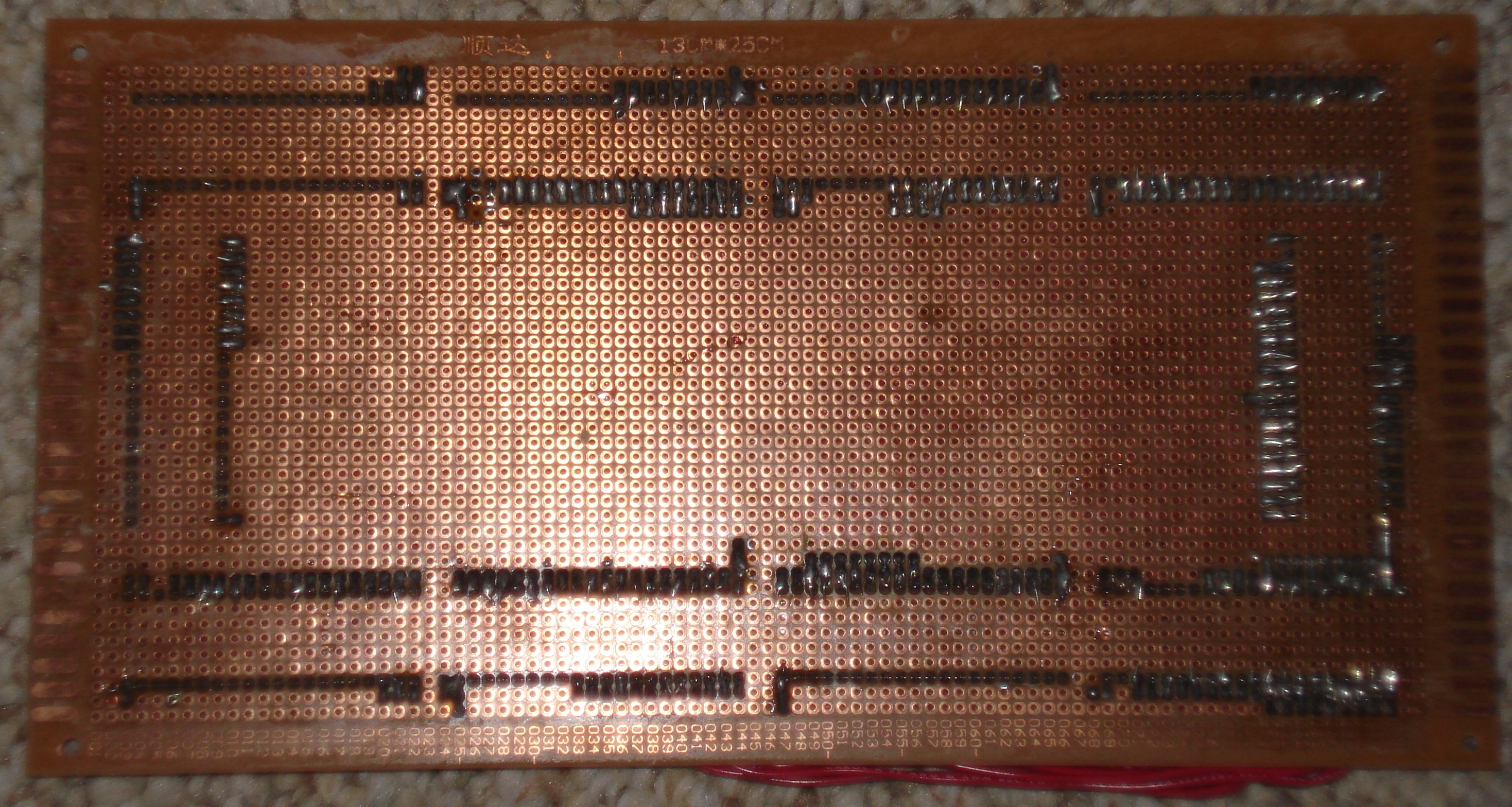
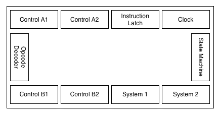
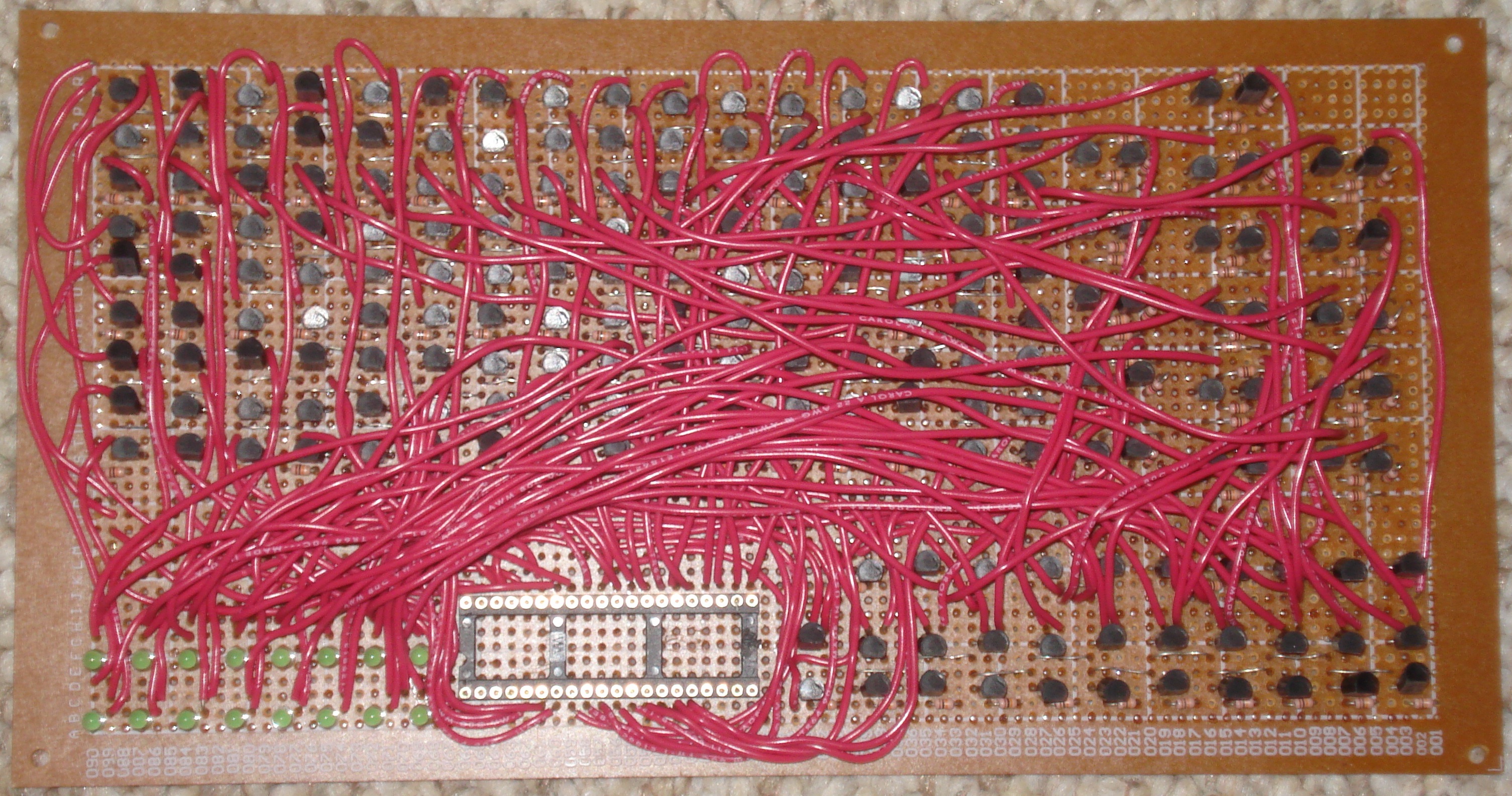
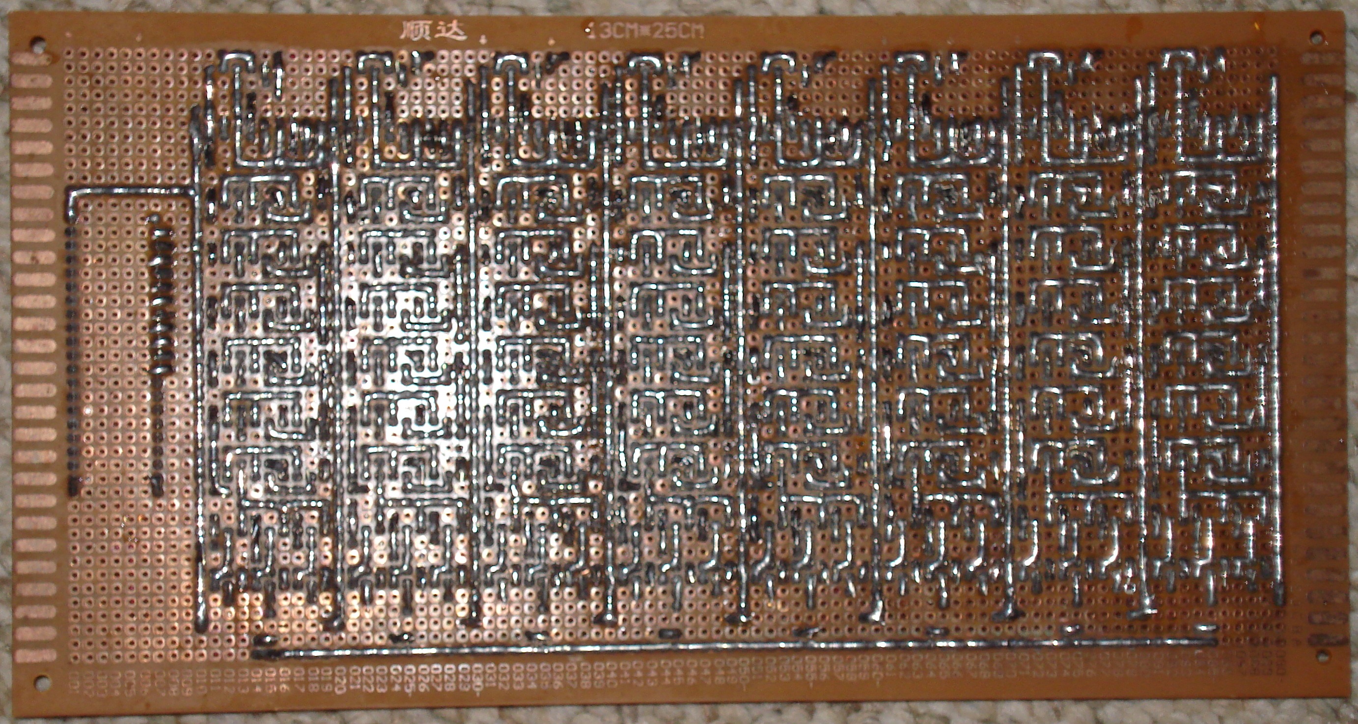
| Control A |
Control line decoder and driver for lines 0 through 12 Control connector 1: Vcc S0 S1 S2 S3 S4 S5 S6 S7 NC NC NC NC NC NC NC NC NC NC NC 1 2 3 4 5 6 7 8 9 10 11 12 13 14 15 16 17 18 19 20 40 39 38 37 36 35 34 33 32 31 30 29 28 27 26 25 24 23 22 21 F0 F1 F2 F3 F4 F5 F6 F7 F8 ~F0 ~F1 ~F2 ~F3 ~F4 ~F5 ~F6 ~F7 ~F8 NC GNDControl connector 2: Vcc L0 L1 L2 L3 L4 L5 L6 L7 L8 L9 L10 L11 L12 NC NC NC NC NC NC 1 2 3 4 5 6 7 8 9 10 11 12 13 14 15 16 17 18 19 20 40 39 38 37 36 35 34 33 32 31 30 29 28 27 26 25 24 23 22 21 I0 I1 I2 I3 I4 I5 I6 I7 C0 C1 C2 C3 NC NC NC NC NC TB WC GND |
122 transistors 42 10k resistors 13 1k resistors 13 LEDs 2 sockets |
Top Bottom |
| Control B |
Control line decoder and driver for lines 13 through 21 Control connector 1: Vcc S0 S1 S2 S3 S4 S5 S6 S7 C0 C1 C2 C3 NC NC NC NC CF NF ZF 1 2 3 4 5 6 7 8 9 10 11 12 13 14 15 16 17 18 19 20 40 39 38 37 36 35 34 33 32 31 30 29 28 27 26 25 24 23 22 21 F0 F1 F2 F3 F4 F5 F6 F7 F8 ~F0 ~F1 ~F2 ~F3 ~F4 ~F5 ~F6 ~F7 ~F8 NC GNDControl connector 2: Vcc L13 L14 L15 L16 L17 L18 L19 L20 L21 I0 I1 I2 I3 I4 I5 I6 I7 TB WC 1 2 3 4 5 6 7 8 9 10 11 12 13 14 15 16 17 18 19 20 40 39 38 37 36 35 34 33 32 31 30 29 28 27 26 25 24 23 22 21 NC NC NC NC NC NC NC NC NC NC NC NC NC NC NC NC NC NC NC GND |
119 transistors 52 10k resistors 10 1k resistors 10 LEDs 2 sockets |
Top Bottom |
| I Register |
8-bit register with one positive/negative input and
constant output. Control connector: Vcc ~I0 ~I1 ~I2 ~I3 ~I4 ~I5 ~I6 ~I7 NC NC NC NC NC NC NC NC NC NC NC 1 2 3 4 5 6 7 8 9 10 11 12 13 14 15 16 17 18 19 20 40 39 38 37 36 35 34 33 32 31 30 29 28 27 26 25 24 23 22 21 O0 O1 O2 O3 O4 O5 O6 O7 I0 I1 I2 I3 I4 I5 I6 I7 WR NC NC GND |
80 transistors 72 10k resistors 8 1k resistors 8 LEDs 1 socket |
Top Bottom |
| Opcode Decoder |
One 4-to-4 decoder for the instruction class and one 4-to-9
decoder for the function.
Positive/negative function outputs are provided to ease
control line decoding. Control connector: Vcc I0 I1 I2 I3 I4 I5 I6 I7 C0 C1 C2 C3 NC NC NC NC NC NC NC 1 2 3 4 5 6 7 8 9 10 11 12 13 14 15 16 17 18 19 20 40 39 38 37 36 35 34 33 32 31 30 29 28 27 26 25 24 23 22 21 F0 F1 F2 F3 F4 F5 F6 F7 F8 ~F0 ~F1 ~F2 ~F3 ~F4 ~F5 ~F6 ~F7 ~F8 NC GND |
82 transistors 64 10k resistors 1 socket |
Top Bottom |
| Control |
Control board. This connects all the control modules together. System connector 1: Vcc RST HLT STP D0 D1 D2 D3 D4 D5 D6 D7 ~D0 ~D1 ~D2 ~D3 ~D4 ~D5 ~D6 ~D7 1 2 3 4 5 6 7 8 9 10 11 12 13 14 15 16 17 18 19 20 40 39 38 37 36 35 34 33 32 31 30 29 28 27 26 25 24 23 22 21 CF NF ZF F0 F1 F2 F3 F4 F5 F6 F7 F8 NC NC NC NC NC NC NC GNDSystem connector 2: Vcc L0 L1 L2 L3 L4 L5 L6 L7 L8 L9 L10 L11 L12 L13 L14 L15 L16 L17 L18 1 2 3 4 5 6 7 8 9 10 11 12 13 14 15 16 17 18 19 20 40 39 38 37 36 35 34 33 32 31 30 29 28 27 26 25 24 23 22 21 L19 L20 L21 NC NC NC NC NC NC NC NC NC NC NC NC NC NC NC NC GND |
10 sockets |
Top Bottom Layout |
System Modules
| Module | Description | Parts | Images |
|---|---|---|---|
| XH Register |
8-bit register with two positive/negative inputs and two open
collector gated outputs (one connected to each of the inputs). System connector: Vcc RA WA A0 A1 A2 A3 A4 A5 A6 A7 ~A0 ~A1 ~A2 ~A3 ~A4 ~A5 ~A6 ~A7 NC 1 2 3 4 5 6 7 8 9 10 11 12 13 14 15 16 17 18 19 20 40 39 38 37 36 35 34 33 32 31 30 29 28 27 26 25 24 23 22 21 RB WB B0 B1 B2 B3 B4 B5 B6 B7 ~B0 ~B1 ~B2 ~B3 ~B4 ~B5 ~B6 ~B7 NC GND |
160 transistors 72 10k resistors 8 1k resistors 8 LEDs 1 socket |
N/A |
| XL Register |
8-bit register with two positive/negative inputs and two open
collector gated outputs (one connected to each of the inputs). System connector: Vcc RA WA A0 A1 A2 A3 A4 A5 A6 A7 ~A0 ~A1 ~A2 ~A3 ~A4 ~A5 ~A6 ~A7 NC 1 2 3 4 5 6 7 8 9 10 11 12 13 14 15 16 17 18 19 20 40 39 38 37 36 35 34 33 32 31 30 29 28 27 26 25 24 23 22 21 RB WB B0 B1 B2 B3 B4 B5 B6 B7 ~B0 ~B1 ~B2 ~B3 ~B4 ~B5 ~B6 ~B7 NC GND |
160 transistors 72 10k resistors 8 1k resistors 8 LEDs 1 socket |
N/A |
| P Register |
16-bit register with one positive/negative input, one open
collector gated output connected to the input and reset. System connector: Vcc RST RD WR A0 A1 A2 A3 A4 A5 A6 A7 A8 A9 A10 A11 A12 A13 A14 A15 1 2 3 4 5 6 7 8 9 10 11 12 13 14 15 16 17 18 19 20 40 39 38 37 36 35 34 33 32 31 30 29 28 27 26 25 24 23 22 21 N0 N1 N2 N3 N4 N5 N6 N7 N8 N9 N10 N11 N12 N13 N14 N15 NC NC NC GND |
208 transistors 112 10k resistors 16 1k resistors 16 LEDs 1 socket |
Top Bottom |
| NH Register |
8-bit buffered incrementor with one input, one open collector gated
output tied to the input, and carry in. System connector: Vcc RD WR CI A0 A1 A2 A3 A4 A5 A6 A7 NC NC NC NC NC NC NC RST 1 2 3 4 5 6 7 8 9 10 11 12 13 14 15 16 17 18 19 20 40 39 38 37 36 35 34 33 32 31 30 29 28 27 26 25 24 23 22 21 NC NC NC NC NC NC NC NC NC NC NC NC NC NC NC NC NC NC NC GND |
232 transistors 144 10k resistors 8 1k resistors 8 LEDs 1 socket |
Top Bottom |
| NL Register |
8-bit buffered incrementor with one input, open open collector gated
output tied to the input, and carry out. System connector: Vcc RD WR CO A0 A1 A2 A3 A4 A5 A6 A7 NC NC NC NC NC NC NC NC 1 2 3 4 5 6 7 8 9 10 11 12 13 14 15 16 17 18 19 20 40 39 38 37 36 35 34 33 32 31 30 29 28 27 26 25 24 23 22 21 NC NC NC NC NC NC NC NC NC NC NC NC NC NC NC NC NC NC RST GND |
232 transistors 144 10k resistors 8 1k resistors 8 LEDs 1 socket |
Top Bottom |
| OH Register |
8-bit register with one positive/negative input and one open
collector gated output. System connector: Vcc O0 O1 O2 O3 O4 O5 O6 O7 NC NC NC NC NC NC NC NC NC NC NC 1 2 3 4 5 6 7 8 9 10 11 12 13 14 15 16 17 18 19 20 40 39 38 37 36 35 34 33 32 31 30 29 28 27 26 25 24 23 22 21 NC WR RD I0 I1 I2 I3 I4 I5 I6 I7 ~I0 ~I1 ~I2 ~I3 ~I4 ~I5 ~I6 ~I7 GND |
88 transistors 48 10k resistors 8 1k resistors 8 LEDs 1 socket |
Top Bottom |
| OL Register |
8-bit register with one positive/negative input and one open
collector gated output. System connector: Vcc WR RD I0 I1 I2 I3 I4 I5 I6 I7 ~I0 ~I1 ~I2 ~I3 ~I4 ~I5 ~I6 ~I7 NC 1 2 3 4 5 6 7 8 9 10 11 12 13 14 15 16 17 18 19 20 40 39 38 37 36 35 34 33 32 31 30 29 28 27 26 25 24 23 22 21 NC O0 O1 O2 O3 O4 O5 O6 O7 NC NC NC NC NC NC NC NC NC NC GND |
88 transistors 48 10k resistors 8 1k resistors 8 LEDs 1 socket |
Top Bottom |
| Front Panel |
Front panel Data path connector: Vcc RST STP HLT ID VD DP I0 I1 I2 I3 I4 I5 I6 I7 NC NC NC NC NC 1 2 3 4 5 6 7 8 9 10 11 12 13 14 15 16 17 18 19 20 40 39 38 37 36 35 34 33 32 31 30 29 28 27 26 25 24 23 22 21 O0 O1 O2 O3 O4 O5 O6 O7 NC NC NC NC NC NC NC NC NC VA IA GNDAddress path connector: Vcc IA I0 I1 I2 I3 I4 I5 I6 I7 I8 I9 I10 I11 I12 I13 I14 I15 VA NC 1 2 3 4 5 6 7 8 9 10 11 12 13 14 15 16 17 18 19 20 40 39 38 37 36 35 34 33 32 31 30 29 28 27 26 25 24 23 22 21 O0 O1 O2 O3 O4 O5 O6 O7 O8 O9 O10 O11 O12 O13 O14 O15 NC NC NC GND |
54 transistors 204 10k resistors 28 .47uF capacitors 25 1k resistors 25 LEDs 27 push buttons 3 toggle switches 2 sockets |
Top Bottom |
| RAM |
RAM board Connects to the data path and address bus modules. Address path connector: Vcc A0 A1 A2 A3 A4 A5 A6 A7 A8 A9 A10 A11 A12 A13 A14 A15 NC NC NC 1 2 3 4 5 6 7 8 9 10 11 12 13 14 15 16 17 18 19 20 40 39 38 37 36 35 34 33 32 31 30 29 28 27 26 25 24 23 22 21 NC NC NC NC NC NC NC NC NC NC NC NC NC NC NC NC NC NC NC GNDData path connector: Vcc ~OE ~WE D0 D1 D2 D3 D4 D5 D6 D7 NC NC NC NC NC NC NC NC NC 1 2 3 4 5 6 7 8 9 10 11 12 13 14 15 16 17 18 19 20 40 39 38 37 36 35 34 33 32 31 30 29 28 27 26 25 24 23 22 21 NC NC NC NC NC NC NC NC NC NC NC NC NC NC NC NC NC NC NC GND |
2 transistors 2 10k resistors 2 .47uF capacitors 4 sockets |
Top Bottom |
| Data path |
Data path controller. Front panel connector: Vcc RST STP HLT ID VD DP I0 I1 I2 I3 I4 I5 I6 I7 NC NC NC NC NC 1 2 3 4 5 6 7 8 9 10 11 12 13 14 15 16 17 18 19 20 40 39 38 37 36 35 34 33 32 31 30 29 28 27 26 25 24 23 22 21 O0 O1 O2 O3 O4 O5 O6 O7 NC NC NC NC NC NC NC NC NC VA IA GNDSystem connector: Vcc RST STP WR RD D0 D1 D2 D3 D4 D5 D6 D7 NC NC NC NC NC NC HLT 1 2 3 4 5 6 7 8 9 10 11 12 13 14 15 16 17 18 19 20 40 39 38 37 36 35 34 33 32 31 30 29 28 27 26 25 24 23 22 21 N0 N1 N2 N3 N3 N4 N5 N6 N7 NC NC NC NC NC NC NC NC NC NC GNDMemory connector: Vcc ~OE ~WE D0 D1 D2 D3 D4 D5 D6 D7 NC NC NC NC NC NC NC NC NC 1 2 3 4 5 6 7 8 9 10 11 12 13 14 15 16 17 18 19 20 40 39 38 37 36 35 34 33 32 31 30 29 28 27 26 25 24 23 22 21 NC NC NC NC NC NC NC NC NC NC NC NC NC NC NC NC NC NC NC GND |
141 transistors 77 10k resistors 8 diodes 1 .47uF capacitor 3 sockets |
Top Bottom |
| Address path |
Address bus controller. Front panel connector: Vcc IA I0 I1 I2 I3 I4 I5 I6 I7 I8 I9 I10 I11 I12 I13 I14 I15 VA NC 1 2 3 4 5 6 7 8 9 10 11 12 13 14 15 16 17 18 19 20 40 39 38 37 36 35 34 33 32 31 30 29 28 27 26 25 24 23 22 21 O0 O1 O2 O3 O4 O5 O6 O7 O8 O9 O10 O11 O12 O13 O14 O15 NC NC NC GNDSystem connector: Vcc A0 A1 A2 A3 A4 A5 A6 A7 A8 A9 A10 A11 A12 A13 A14 A15 NC NC NC 1 2 3 4 5 6 7 8 9 10 11 12 13 14 15 16 17 18 19 20 40 39 38 37 36 35 34 33 32 31 30 29 28 27 26 25 24 23 22 21 N0 N1 N2 N3 N4 N5 N6 N7 N8 N9 N10 N11 N12 N13 N14 N15 NC NC NC GNDMemory connector: Vcc NC NC NC NC NC NC NC NC NC NC NC NC NC NC NC NC NC NC NC 1 2 3 4 5 6 7 8 9 10 11 12 13 14 15 16 17 18 19 20 40 39 38 37 36 35 34 33 32 31 30 29 28 27 26 25 24 23 22 21 A0 A1 A2 A3 A4 A5 A6 A7 A8 A9 A10 A11 A12 A13 A14 A15 NC NC NC GND |
144 transistors 80 10k resistors 2 .47uF capacitors 3 sockets |
Top Bottom |
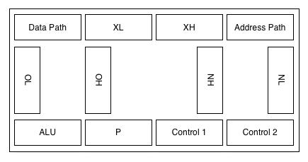
| System | System board. This connects the whole thing together. | 12 sockets |
Top Bottom Layout |
| Power Supply | Power supply. 5 volts, 3.0 amps. | N/A |
Parts Summary
| Part | Number |
|---|---|
| PN2222A NPN transistors | 3105 |
| 10k resistors (1/4 watt) | 1835 |
| 1k resistors (1/4 watt) | 163 |
| LEDs | 158 |
| 40-pin sockets | 68 |
| 13x25 cm boards | 30 |
| DS1270Y-100 SRAM | 1 |